
Introduction
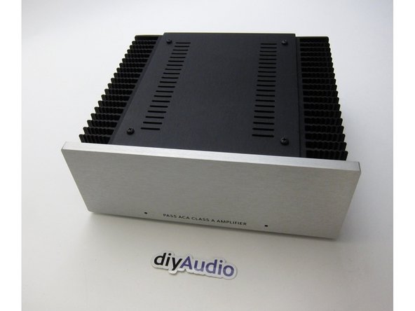
This is the build guide for the Amp Camp Amp v1.6.
The differences between the 1.5 and 1.6 are fairly minor - the circuit is identical to the previous version, all the parts other than some chassis mounted components are the same. The schematic is the same, and part numbers are the same. The biggest changes are a different layout of the PCB, inclusion a front mount power switch, and the rear switch is now used for RCA input stereo/mono.
Please note that the wire colors have changed in batch 3. While some colors are unchanged, there are now more unique color pairs, and we have updated the wiring diagrams with the new colors, however the photos and videos in the guide have not yet been updated. Please print out the correct wiring diagram to match your batch (steps 33 and 34), and refer to it while you build.
If you have any comments or tips on any step please leave a comment. Please note you must first be logged in to diyAudio before you post your comment here. Your comment may be invaluable to other builders!
-
-
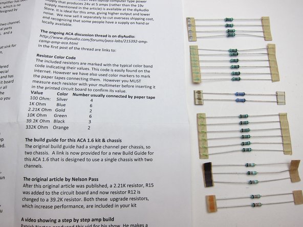
Print this out on paper and have it in front of you during the whole process.
-
-
-
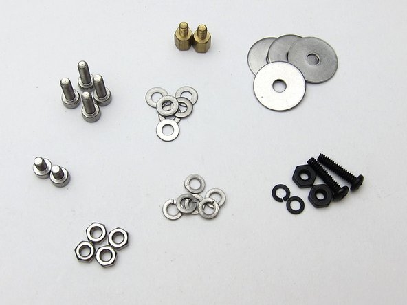
The various components are all found in individual bags as shown.
Hi! I was supplied 2x extra 332k resistors and am missing 2s 10k resistors.
Also - I soldered power resistors snug to the PCB and only afterwards saw a note in the build guide to allow 1-2mm space as they get hot during use and will damage PCB. I’ve already trimmed them too short to now allow and space. Would it be possible to receive replacements for those as well? That’s 2x .47 resistors and 2x .68 resistors. Or is it OK to leave that?
Can someone point me to the Parts document that lists the resistor, capacitor values and their exact locations on the board pls? I’ve seen snippets of it in some assembly photos and it’s labelled Parts List but it didn’t come with my kit and I can’t seem to find where to download it at DIYaudio.com
I’m struggling with reading the schematic and the photos of the finished boards in the assembly instruction aren’t high enough quality to use to identify the color bands on the various resistors. I have the most current version from 8/19 and am using it as a stereo build. Thanks- I think I accidentally miss read the color bands on two resistors and soldered them in the wrong spots and had to unsolder them etc.
thanks
The document that has exactly what you are asking about is the schematic. :) The PCB is labeled with the parts locations, and the numbers on the PCB match the schematic.
As for identifying the resistors, use your multimeter set to ohms and measure them.
Also remember you can click into the photo for high resolution.
6L6 -
-
-
-
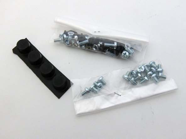
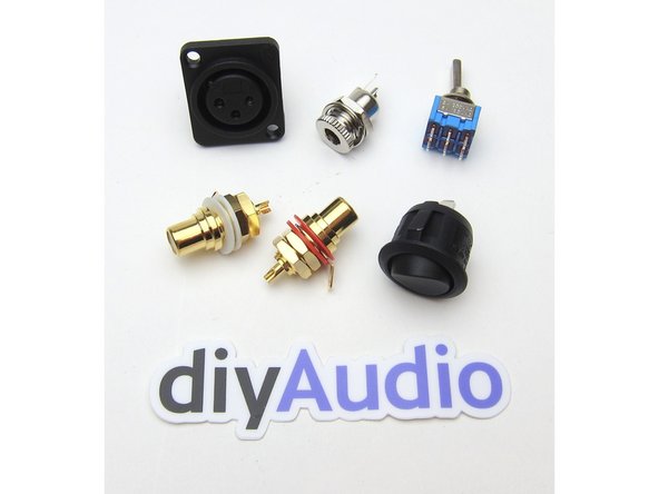
In the various bags of the kits you will find hardware,
-
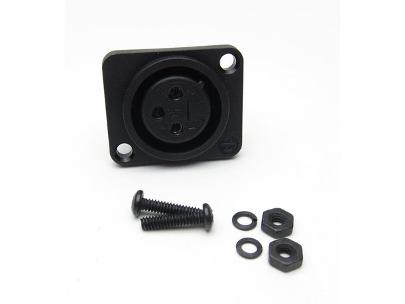
The XLR jack,
-
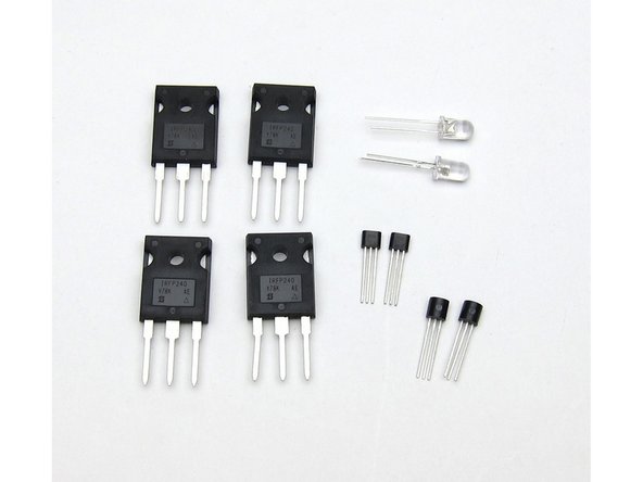
The transistors and LEDs.
-
The big transistors are the Mosfets (Q1 Q2), The smaller of the two other transistors is the ZTX450 (Q3), and the slightly bigger one is the input Jfet (Q4)
The 4 M3 nuts in the 1st picture don’t seem to be used anywhere.
-
-
-
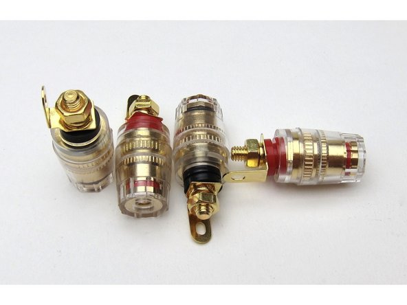
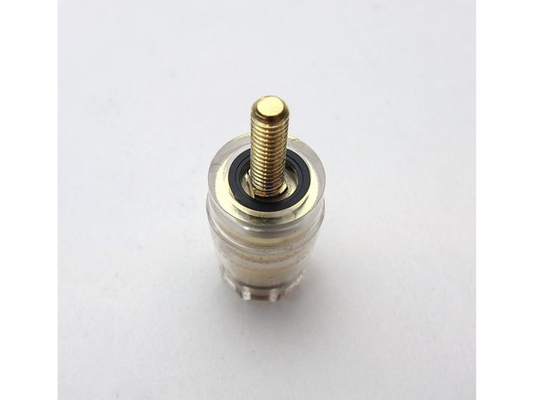
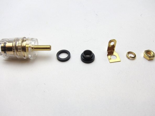
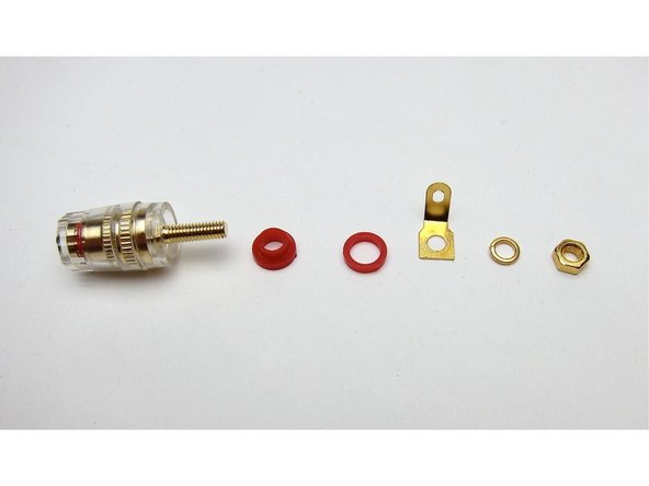
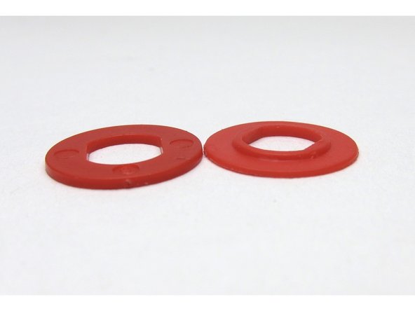
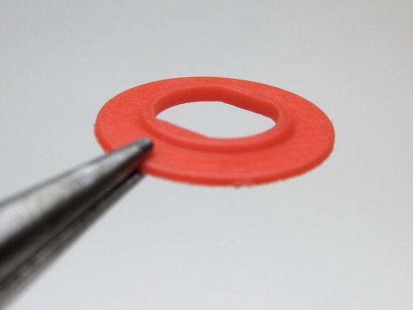
Speaker posts.
-
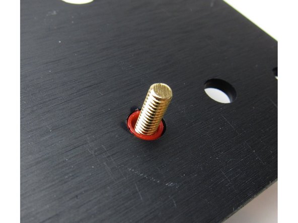
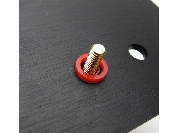
Try the washers in the posts as shown, some posts will fit the small washer flush on this side, some will fit the shoulder washer on this side.
-
It doesn't matter if the shoulder comes first or the other plastic washer, as long as things sit squarely and the shoulder washer is inserted through the chassis so the threaded portion doesn't touch the back panel itself.
-
-
-
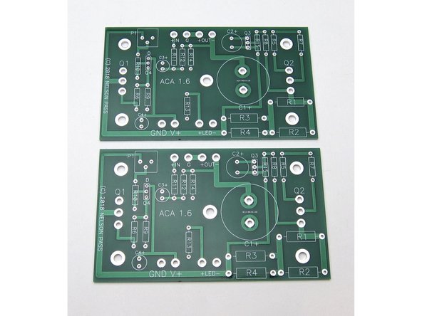
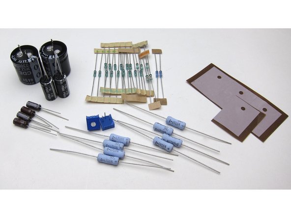
Now we will stuff and solder the components onto the PCB.
-
Get the resistors and capacitors, and place the keratherm insulators aside for the moment.
-
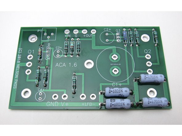
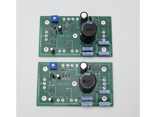
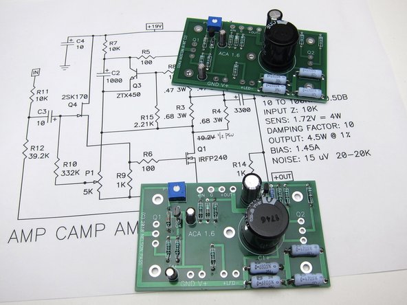
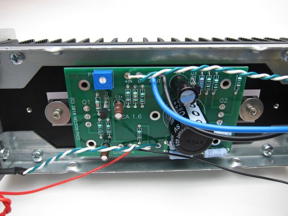
Image 3 shows the two properly stuffed PCB, assisted by the fact that the schematic was printed out and referred to during the whole process. :) :) :)
Jim Tiemann (6L6) has a really good Youtube video on how to solder components onto a printed circuit board and it can be found here: https://www.youtube.com/watch?v=oN_63ixB...
-
-
-
Measure EVERY RESISTOR before placing in the board :)
-
Panasonic power resistors: It's difficult to measure these because the resistance of your multimeter leads (normally 0.2-0.4Ω) will be added. You can measure your leads and subtract the value, just trust the values which are printed on them, or build a low resistance value test rig.
-
Have the schematic printed in front of you at all times. The schematic marked 1.1 is correct for the 1.6
-
The resistor tape is marked in a way shown on the documentation in the box. Measure everything regardless.
I posted this on the nascent 1.8 guide:
I’ve annotated a photo of the board with the resistor measurements. This way it’s really easy to check the resistances before soldering, particularly for the tiny resistors. It means I can skip a mental step and refer to only one document. Plus the board’s resistor numbers are obscured by the actual resistors, which otherwise complicates checking. It seems like an obvious thing to me. I’ve bought two amps, doing four boards, so something like this will make the project easier and more fun for me. I do NOT want to de-solder mistakes.
Has my effort been done? Are all my numbers correct?
For each resistor, how close should the measured resistance be to their intended/marked resistance? Very few of mine measure exactly as marked, but they’re all within a percent, according to my budget multimeter. Good enough?
Each resistor has a tolerance marked on it, and they should be within that tolerance. See https://www.arrow.com/en/research-and-ev... for how to read the tolerance value, and what color indicates which tolerance.
Jason -
Regarding low resistance measurement, I built myself one of these units:
http://www.siliconchip.com.au/Issue/2010...
I grabbed a complete kit from Altronics just because it was easy and (to be honest) an impulse buy … as you do.
it’s a bit more involved (+ more expensive) than the set up pointed to in the second point above but it has the advantage of a millivot reading that’s a 10x multiple of resistance. It switches from 1 mV / mΩ to 1 mV / 10 mΩ, so it makes reading values a lot more straight forward. It’s an alternative anyway.
-
-
-
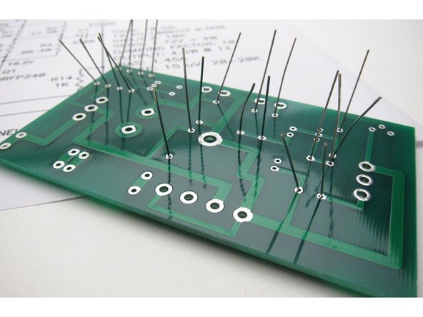
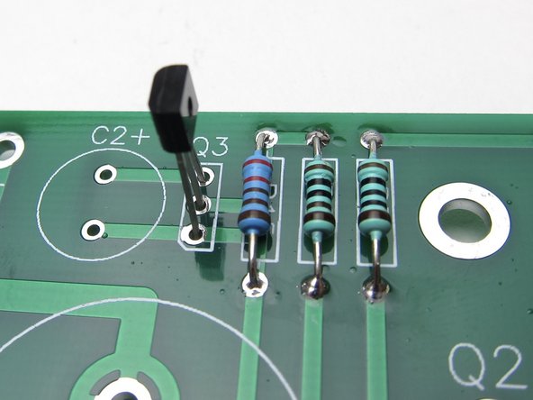
Generally it's easiest to start stuffing the PCBs with the smallest components first - in this case the resistors.
-
Note the 1% resistors all have a brown band at one end - to help assist troubleshooting in the future if needed, place the brown at the bottom of all resistors.
-
Slightly bend out leads before soldering
If you have the suggested Hakko CHP PN-2008 long nose pliers you can get the correct lead spacing for the smaller (non 5 Watt) resistors by pinching each resistor lead with the pliers right next to the resistor body and bending the lead with your fingers to 90 degrees against the pliers. For the 5 watt resistors I found that doing 1 lead like this and bending the other lead at the resistor body gave me the proper spacing.
-
-
-
Please watch this excellent YouTube video on How To Solder from Mr Carlson's Lab for a good how-to-solder video. You are probably looking to have your soldering iron set to 350-400'C.
-
We highly recommended a leaded eutectic solder for many reasons. Please see our guides page on which solder to purchase.
-
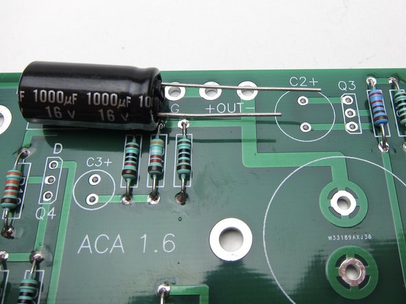
The first photo shows the big and little resistors in their places. Note the large resistors have the value printed right on them - try to bend the leads so the values show and align as shown.
-
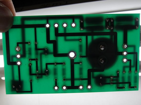
The second photo shows that if you hold the PCB up to the light, you can see if you missed any solder holes
-
Arrange resistors with values upwards, so you can read them after they have been soldered in place.
-
Power resistors: It's difficult to measure these because the resistance of your multimeter leads (normally 0.2-0.4Ω) will be added. You can measure your leads and subtract the value, or read the values which are printed on them.
-
Power resistors: They do get hot and over a long period of time might discolor the PCB. Put a spacer underneath them (like a piece of cardboard) to create an air gap of a few mm, and remove it after soldering them in place.
On the solder- I used the Fire Metall Eutectic to start. It melts easily, but it’s really skinny- 0.020" (0.5mm) diameter. For me it’s a bit awkward- it bends easily, and I needed what seemed like a lot for each hole on the PCB.
Anyway, I had some Cardas Quad eutectic which I went to when wiring the PCB to the front and back panels- much easier for me.
Maybe something to do with being 69, and using an Optivisor over my reading glasses?
If you are 25 I’m sure the Fire Metall is great.
CitizenKane - Thank you, this is a good comment, and I will update the step with more information about this phenomenon. Almost certainly your resistors are not out by 150%, and you are experiencing the limitations of your measuring equipment. Don’t worry, you aren’t the first person to experience this. What other customers have found is that due to the very low resistance value of these power resistors, your testing equipment is giving inaccurate results. Likely you have started to measure the resistance of your testing leads. A customer using a Fluke meter was able to get accurate results by using thicker DIY test leads instead of the ones he was previously using.
Astromo - Thanks for pointing that out.
Wow, not even one power resistors value is inside the tolerance, up to 150% of tolerance.
I wish this post had been up and I'd read before warming up the iron:
Amp Camp Amp - ACA Thread, Post #5971
I found out late (after my build was complete) that I should have been working to an iron temperature of 300 - 350 °C / 570 - 660 °F.
Even so, I got there in the end.
One small detail (also noted by other members in the original thread) is to install the 3W power resistors slightly above the PCB. They become quite warm during operation, so this gap should provide for better cooling - and prevent discoloration of the board over time. A 1-2 mm gap should be sufficient.
-
-
-
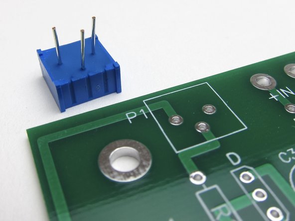
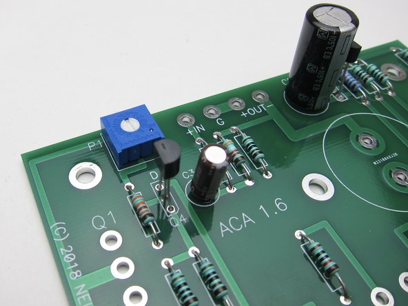
The potentiometers have three leads in a triangular formation, they are impossible to insert backwards.
-
-
-
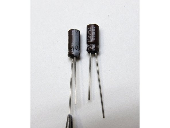
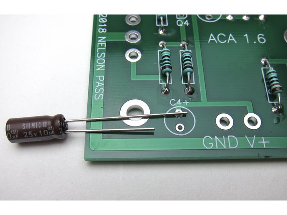
Capacitors have polarity - the long leg is Positive +, and the mark on the can shows negative -
-
Second and third image show: Long leg in the positive marked hole
-
-
-
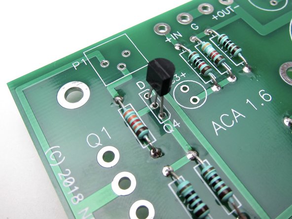
Align the flat of the small transistors with the silkscreen as shown.
-
Q4 is the input Toshiba or LS Jfet, marked K370 or K170 on the flat of the package.
-
Place Q4
-
-
-
Place Q3. ZTX450 Like the other small transistor the flat of the transistor package matches the flat of the silkscreen.
-
-
-
Complete stuffed PCB shown here. Note transistor and capacitor alignment.
-
-
-
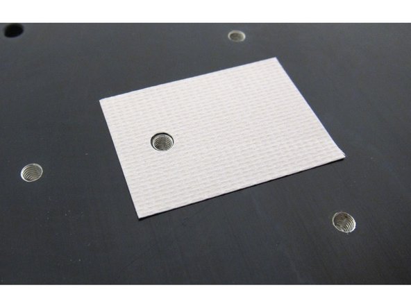
Keratherm is a great modern replacement for the (sometimes toxic and always messy) thermal conducting goop w/insulators required to insulate transistors to heatsinks.
-
The Keratherm is used to electrically insulate the transistor's metal back (Drain) from the metal chassis. And thin enough to allow heat to be transferred from the transistor to the chassis effectively.
-
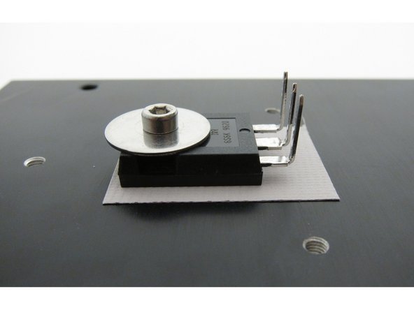
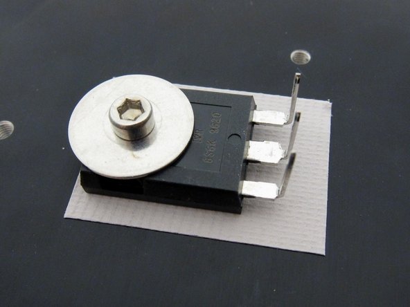
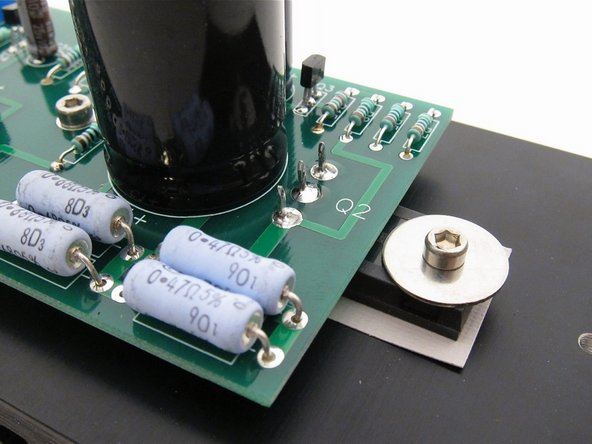
Big transistors mount as shown here, and gently bend the legs up right at the point that they narrow.
-
There should be a lock washer (split washer, spring washer) between the fender washer and the screws.
-
Use a 2.5mm hex wrench to gently tighten the bolts
Where can I get the mounting hole specifications on heatsinks provided with ACA amp kit as I am using my own heatsinks and dont have kit with me?
I just have ACA PCB, but not getting idea for Q1 and Q2 hole distance, please advise if possible.
I guess you’ve already worked it out by now but i had the same question for my build. Did some measurements and studied these pictures of where to bend the mosfet-feet.
My measurements came out like this:
If 0;0mm (x;y) is center of heatsink and also center hole of PCB. Then the other holes turned out like this.
0 ; 0 (Center PCB)
-60;0 (For mosfet)
60; 0 (For mosfet)
-40; -20 (Optional)
-40; 20 (Optional)
40; -20 (Optional)
40; 20 (Optional)
Illustration:
-40;20 40;20
-60;0 0;0 60;0
-40;-20 40;-20
Drill with 2,5mm and tap for M3-thread.
My PCBs is rev 1.6, purchased in July 2023.
I hope this will help others.
/John
If you can see the lock-washer, make sure it’s compressed enough so it’s flat. Much more than that is probably a bit much.
Be careful when tightening the screws. Do not overtighten them as it’s quite easy to squash the keratherm which is rather soft. The recommended tightening torque of these transistors is around 1.1 Nm or 0.8 ft/lbs (assuming a perfectly flat surface). But you don’t have to be scientific, just be careful and trust your feelings.
… and for those (like me) who want even more specifics, plus a lot of theory to digest, here’s great information about Mounting Considerations For Power Semiconductors: https://www.onsemi.com/pub/Collateral/AN...
-
-
-
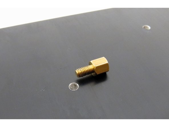
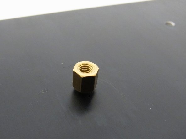
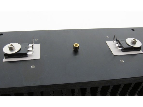
Before mounting circuit board, attach a standoff to the heatsink. Do not over-tighten!
-
It does not have to insert all the way flush into the heatsink.
-
-
-
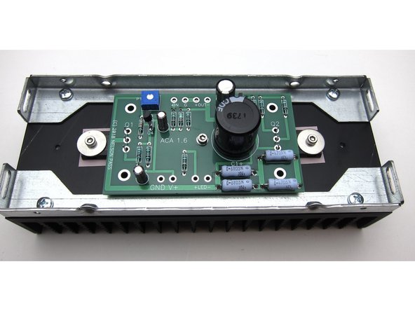
One screw and washer to hold the PCB to the center standoff, and align the big transistor legs with the holes.
-
Solder the transistors.
After soldering Q1 and Q2, do NOT clip off the excess leads. See step 51. You will need to attach your multi-meter to pin 2 of Q1 in order to adjust the pot. I am very pleased that somehow I left these pins intact.
You can mount both to one heatsink. There will be no issues. :)
A better place to discuss questions like this is here - https://www.diyaudio.com/forums/pass-lab...
-
-
-
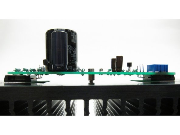
Sit back and take some time to admire the work you've done to date
-
Check that under the PCB there are no leads touching the heatsink (which is grounded)
-
-
-
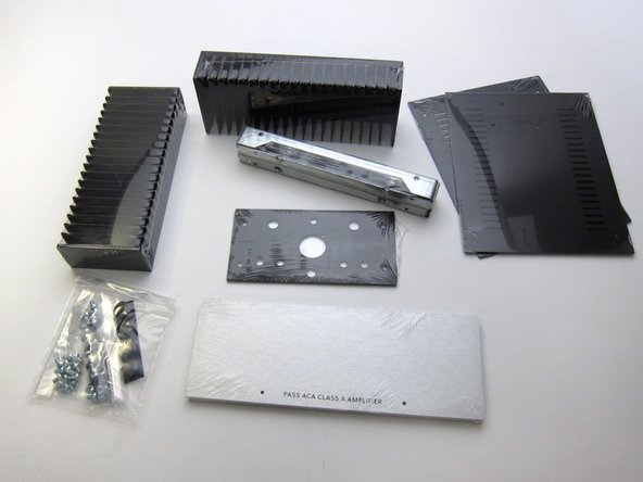
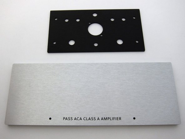
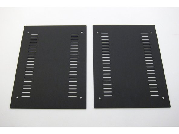
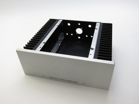
Check you have all the bits. These photos show the front panel without power switch.
-
First image: Chassis contents
-
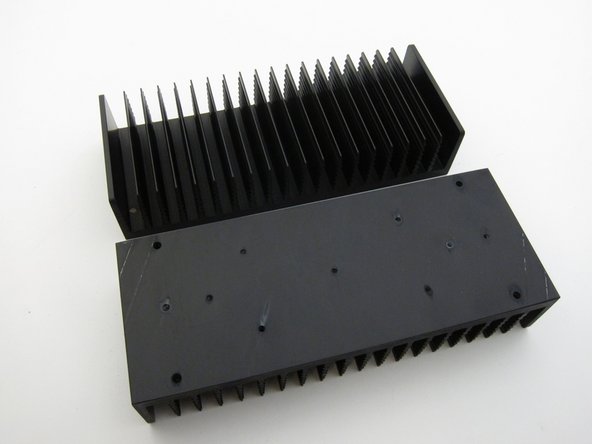
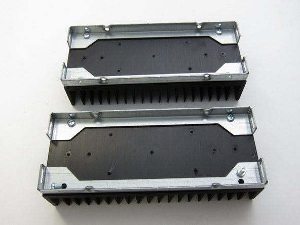
Second image: Heatsink rails
-
Third image: Front and rear panels
I believe all of these chassis assembly instructions are out of order. They should follow assembling/soldering the back-panel.
Suggested order (my very first amp build, so take this and all of my other comments with a grain of salt:
1: Stuff and solder PCBs
2: Fix Q1/Q2 to heatsink
3: Mount PCBs & check for shorts to sink
4: Stuff and wire back panel
5: Attach rails to heat sinks
6: Attach one heatsink to back panel and face plate (P1 pot toward top)
7: Wire back/front panel --> PCB
8: Attach second heatsink to back panel and face plate (P1 pot toward top)
9: Wire back/front panel --> PCB
10: Power up & set bias
11: Attach ventilated top/bottom covers
This is my first build; as soon as I opened the box containing the Chassis, I knew this was going to be a great project with something that will make me very proud (I have another kit as well for four channels of Analogue Synthesis).
I found the guide to be in a strange order as well.
What I found helped me is the following:-
Loosely fit brackets to heatsinks.
Fit front panel to brackets on a FLAT SURFACE and tighten up.
Tighten up heatsinks.
Fit bottom panel - a struggle as a couple of holes needed aligning with the bracket sockets.
Fit Q1 and Q2 etc and place completed PCB on and anchor with screw, but don’t solder anything.
Work out wire lengths and mark up with masking tape for reference.
Remove PCBs and solder wires.
Return PCB to chassis and solder in place to Q1 and Q2.
I found the connection to GND of the Outputs to be counter-intuitive; but I suppose it is the equivalent of having a synth module input tied to GND via a resistor in lieu of an input connection from an upstream module.
-
-
-
First image: Ventilated top and bottom panels
-
Second image: Hardware
-
Third image: Heatsinks
-
-
-
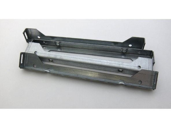
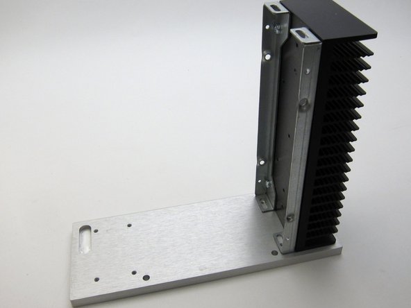
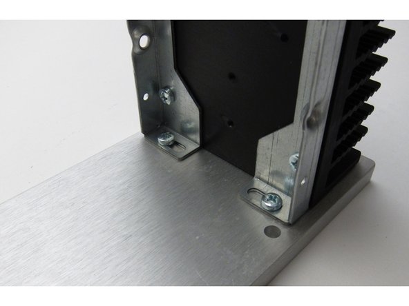
Attach the rails to the heatsinks
-
-
-
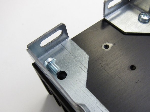
First image: Align slots with the holes in the front panel
-
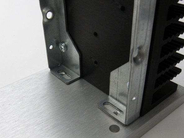
Third image: Screws insert as shown
-
Please note that there is some intended slop in the bracket attachments. This can create slight alignment errors later when you are putting together the finishing touches on the chassis like screwing in the covers.
-
You might need to just tighten these up "fit tight" so you can wiggle them later, when you do a final alignment to get the screw holes in the covers to line up.
I used a number 1 Phillips screwdriver to get the screws started. Then tightened with number 2 Phillips.
Rest both heatsinks on a perfectly flat surface in exactly the same way when screwing them to the front plate. Allow the front plate to hang freely when tightening. You can attach the heatsinks at different times if you do the second exactly as the first. The slop will allow you to adjust the height of the front plate a little.
The covers only attach to the heatsinks. All my holes on the covers and the back plate lined up almost perfectly. When I added the second heat sink I needed to loosen the back plate screws on the other heat sink just a bit, but I did not need to mess with the front plate screws. This is a very well made and thought out enclosure.
-
-
-
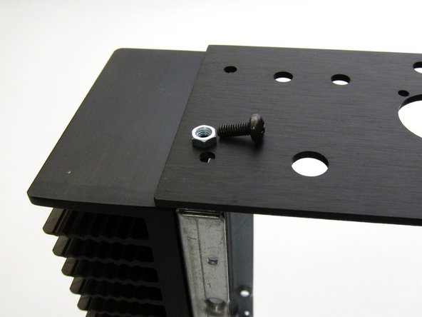
Rear panel attaches with nut and screw
Be sure to note the position of the XLR screws. If you flip the panel, all the posts will go on fine until you get to the XLR… and you’ll have to take everything off and do it again (ask me how I know…). Additionally, I think it’s probably better to wait and attach the rear panel until after all posts are mounted, and possibly at least partially soldered.
-
-
-
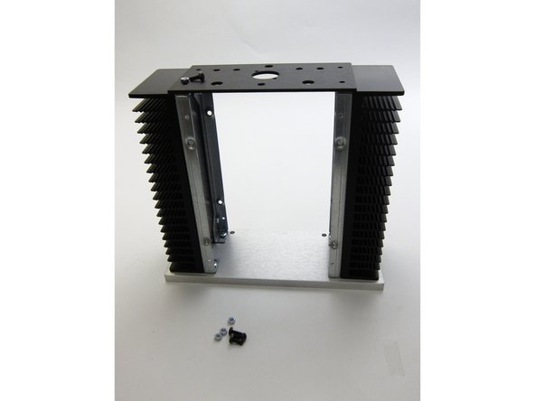
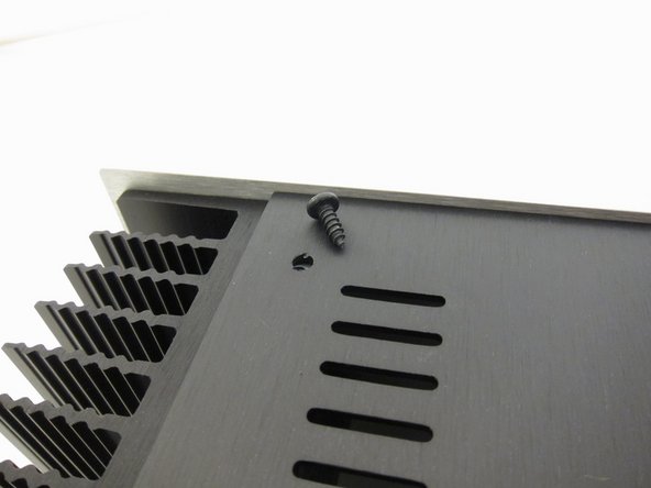
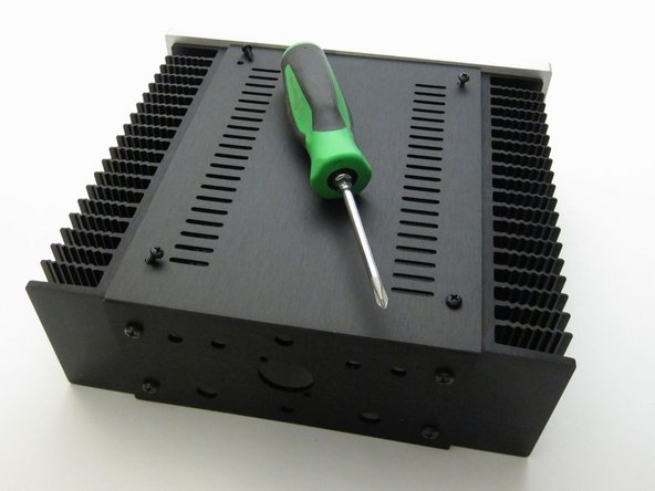
Sheet metal screws attach the top and bottom panels
-
-
-
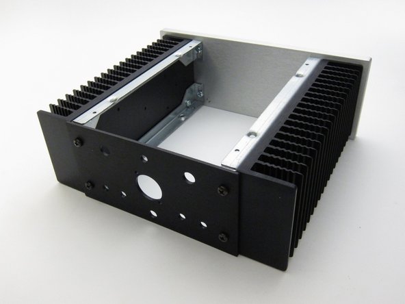
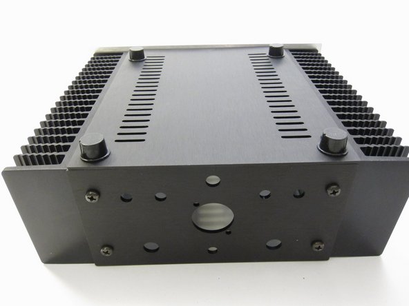
Feet are stick-on
-
-
-
Back panel hardware
-
-
-
Viewing from the inside of the amplifier
-
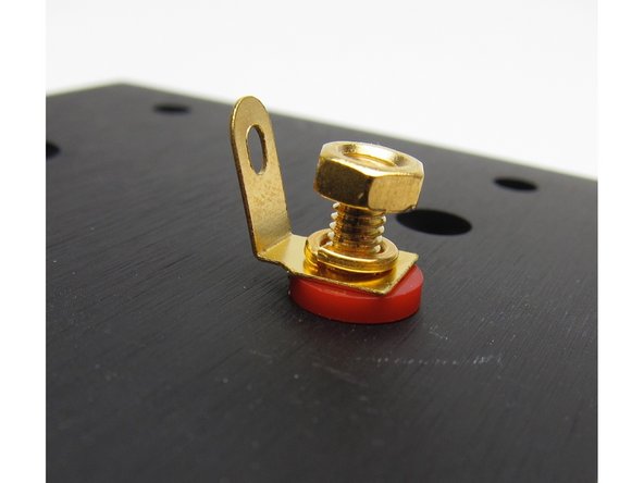
First image: The colored shoulder washer goes on the outside, through the hole. This is to align the post so that no metal touches the chassis. BUT, on some posts things sit more flush if the round washer is on the outside and the shoulder is on the inside - either way is fine, do what aligns better.
-
Second image: Then the other plastic washer
-
Third image: The metal tab sits upon the plastic, then lockwasher, and nut
Align the holes of the posts where the speaker wires will connect verticaly on the outside before tightening the nuts from the inside.
The way I installed the colored plastic washers was to install the larger (non-stepped) washer on the outside of the case - it fits perfectly tight up inside the clear plastic of the binding post and its color shows through the clear plastic of the binding post. Then I installed the stepped washer on the inside so there is no slop in the clearance around the threaded post. It insulates just as well either way, but this way everything is tight and there is not the extra clearance seen in the second picture above between the large washer and the threaded post. Seemed like that was the way it was designed to be installed.
The XLR plug is directional, it only orients properly when the correct side of the backplate is facing the proper direction. Before you start mounting the various backplate components, take a moment and figure out which sides will be the inside in and outside by fitting the XLR plug and seeing which way orients the plug properly. You can mark the inside of the plate for reference.
-
-
-
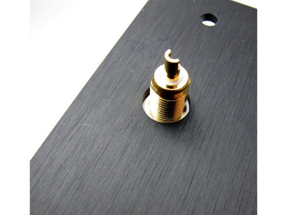
Align the hole in the post to be vertical.
-
-
-
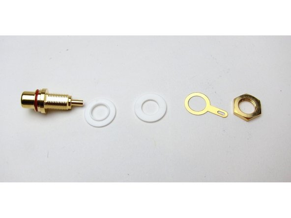
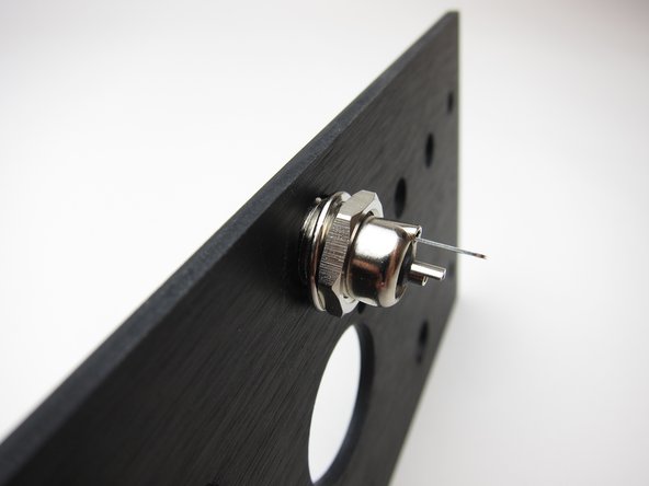
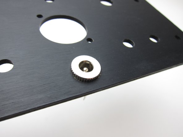
First image: RCA post hardware
-
Second image: Again, viewing from the inside, the shoulder washer sits in the hole and keeps the metal of the RCA from touching the chassis
Woops. Should have applied to speaker terminals not RCAs.
V1.8 July 2020 purchase
Both the post and the tab want to turn when getting tight, and the tab wants to hang down. I held the back plate securely upside down on edge on my solder mat so the tab would hang down (result up), then I held a skinny screwdriver through the post hole into the mat. A spare finger kept the tabs down.
I used a 7mm nut driver in my case. I also put the stepped washers inside the case.
I am populating the back plate first before soldering any wires. I hope to have the 1.8 wiring diagram figured out before that.
-
-
-
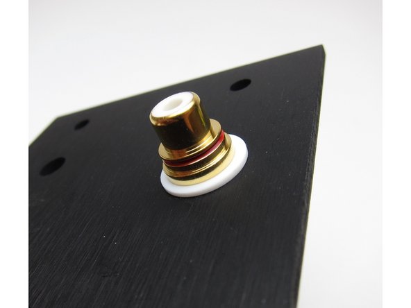
Interior view
-
Note raised bit (shoulder) on one RCA washers, this must face the inside of the hole to keep the assemble aligned and insulated properly
-
-
-
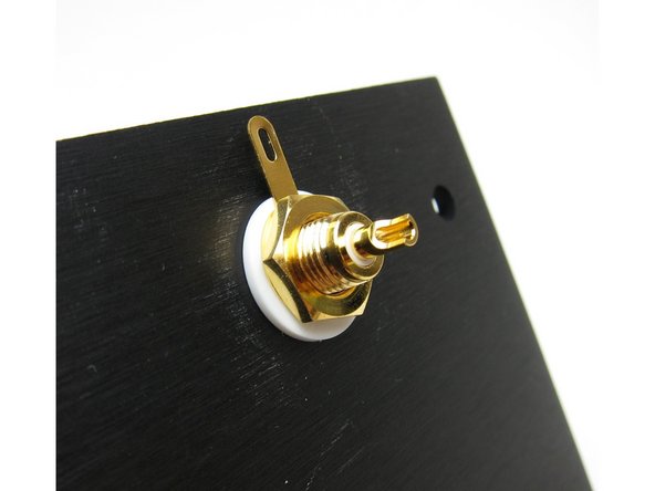
First image: split (lock) washer under the nut
-
Second image: outside of the chassis
-
Third image: Align so the tab is up, closer to the XLR
-
-
-
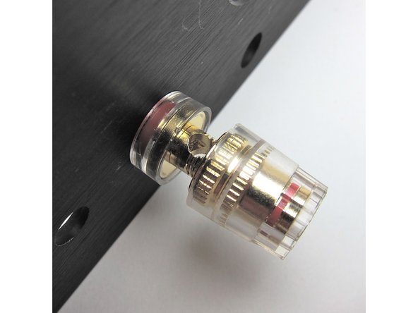
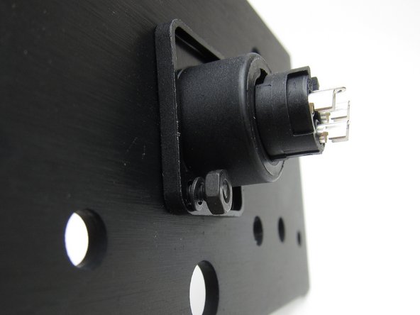
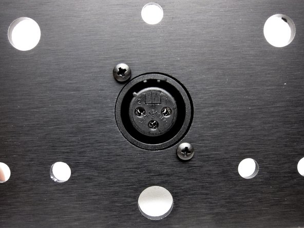
The XLR can mount inside or outside as you desire. Mounting inside will give a flush exterior.
-
-
-
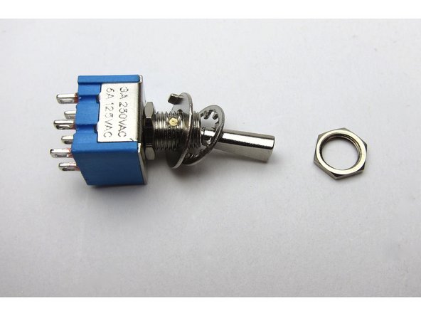
The rear switch is included in the kit as an "option" switch. This is a DIY project and you get to choose what that option is. Regardless of whether you are making an ACA with a front power switch or not, this toggle switch can optionally be configured by yourself to:
-
Switch the amp on and off
-
Switch between mono/stereo operation
-
Dim the LED
-
Etc
-
For simplicity in this guide which is focused on the "ACA with front power switch" configuration, from step 35 onwards, this toggle switch will be used to toggle between stereo and bridged mono operation when using RCA input. (XLR does not need the switch)
-
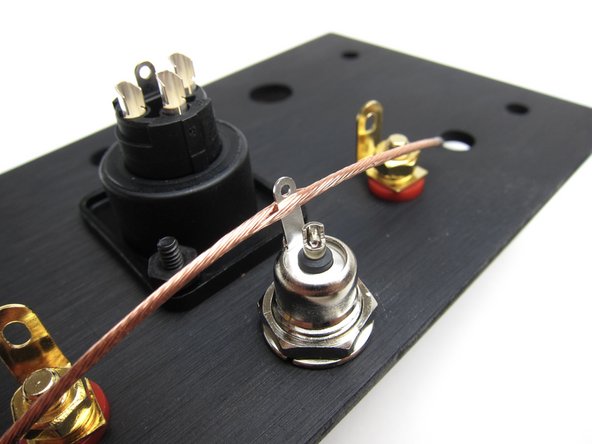
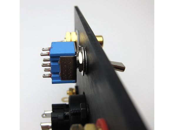
Look closely at the arrangement of washers and nuts. The rearmost nut adjusts switch depth, the big washer is keyed and the tab needs to point to the body of the switch, and then the lockwasher is up against the back panel. The last nut is for the outside of the back panel.
-
Mount as shown
-
-
-
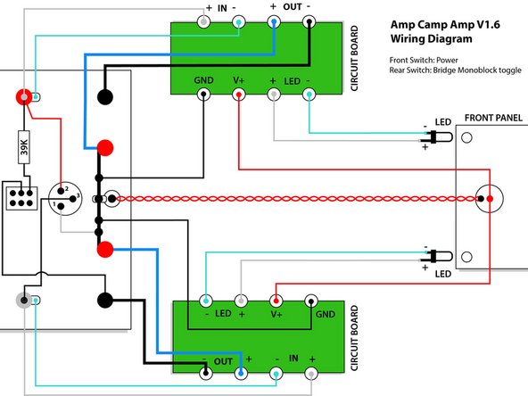
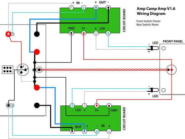
This is the wiring diagram for batch 1 & 2. You have one of these batches if your kit shipped before Nov 20th 2018. If your kit shipped after this date (if so, your kit will include grey wire), please skip to the next step for the correct wiring diagram for your kit.
-
Please download the ACA V1.6 Batch 1 & 2 Wiring Diagram PDF, which shows 3 wiring options:
-
A) Front switch: Power; Rear switch: Bridge monoblock toggle
-
B) Front switch: Power; Rear switch: None
-
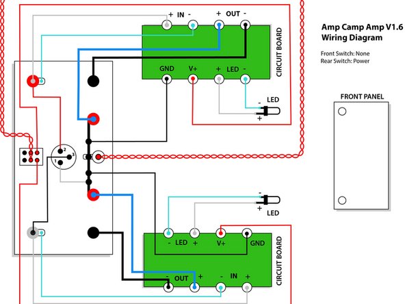
C) Front switch: None; Rear switch: Power
-
This guide mainly shows option A
Answer from 6L6 : «Nevermind, it works both ways»
Build “C” (Front switch: None / Rear Switch: Power – the diagram shows the switch being hooked to the DC input in the middle pins, and the connection to the PCB in the 2 pins below (near the XLR).
BUT the FOTO @ step 36 is the opposite (while the sketch @ step 36 shows it like in the diagram.
Which is right?
Both ways will work fine. If one was forced to choose, wire as shown the photo.
6L6 -
-
-
-
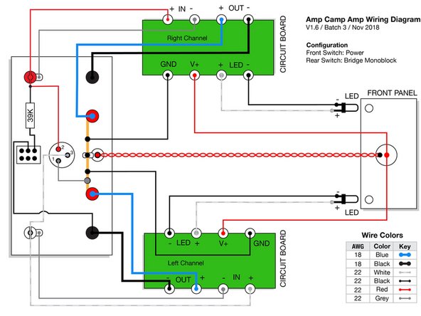
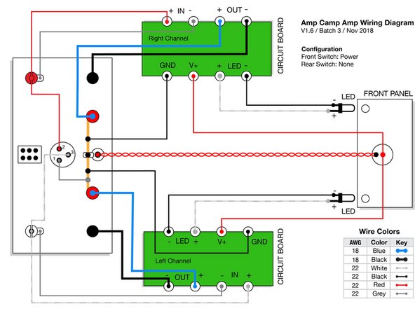
This is the wiring diagram for batch 3. You have batch 3 if your kit shipped after Nov 20th 2018 and your kit contains some grey wire.
-
Please download the ACA V1.6 Batch 3 Wiring Diagrams PDF and print out the correct wiring diagram for your amp.
-
Batch 3 includes one new color (grey). This allows for more unique color pairs and the ability to keep signal paths a similar color.
-
However, this means the wire colors in the pictures and videos in this guide will not match the wire you have received. Please be careful to always consult your wiring guide diagram, and do not assume the wire colors in the photos are correct for your kit.
-
We will update the photos and videos at some point in the future, please bear with us.
-
-
-
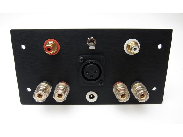
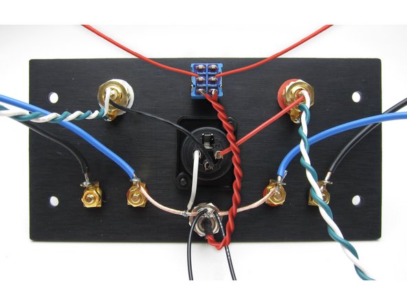
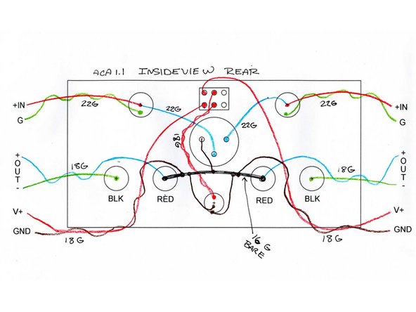
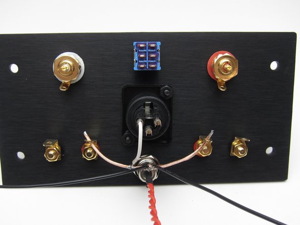
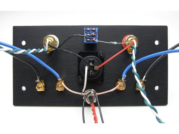
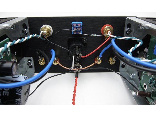
This shows everything attached to the back panel in the proper positions.
-
Yes, the red RCA is on the left when looking at the back - this is to have it on the proper side when the amp is facing forward.
-
XLR - this shows it mounted to the outside, but you may inside mount it as well if you desire, there's no benefit one way or the other.
-
Speaker jacks - REDs are mounted INBOARD, blacks to the outside
-
-
-
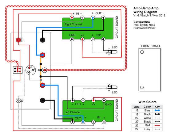
The image and diagram in this step is ONLY for people building the ACA with no front power switch.
-
With no front power switch, your wiring is simpler, and we will use the rear toggle switch for power only.
-
Please review the image and wiring diagram carefully. The DC jack is a bit ambiguous - to be clear, the red goes to the center pin and black to the outer tab.
-
The only significant difference between your build and the pictures shown in the rest of this guide are that your V+ wires will come from the rear switch, instead of the front switch.
-
If you want to bridge your amp this is no problem, please see step 46 of the ACA 1.5 build guide for how to make an external bridging connector.
-
If you are building your ACA with a front power switch, please ignore this step and its images entirely.
-
-
-
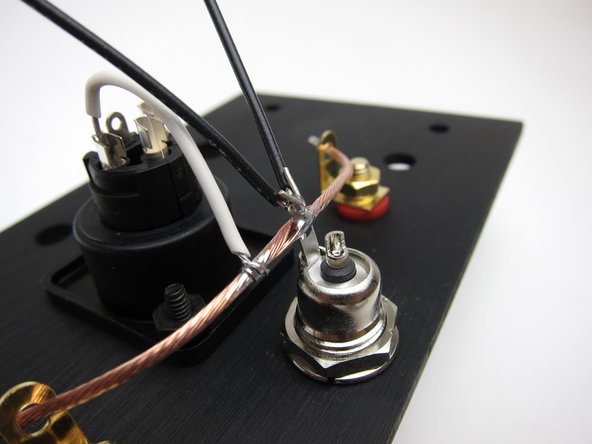
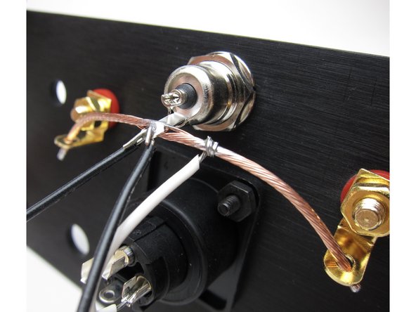
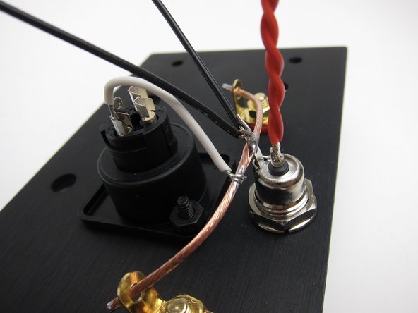
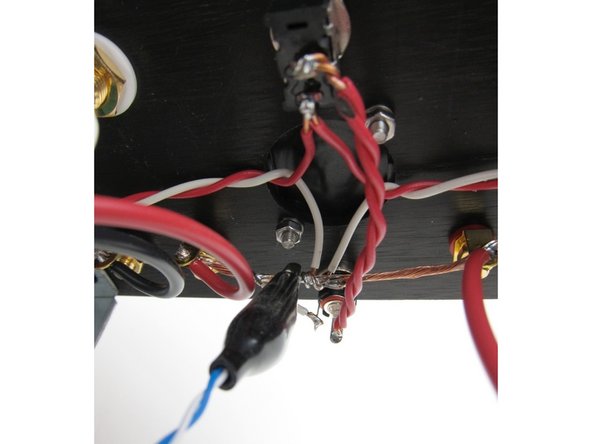
To create the ground buss cut a length from the heaviest gauge wire and strip the insulation off
-
The tab of the barrel connector should be "up". The wire may be soldered to the tab now, but don't solder it into the red (inboard) speaker jacks until you have the other speaker wires to the PCBs
-
Image 2 - Connect pin 1 of the XLR to the buss wire. Then connect 2 lengths of wire to the ground buss - these will connect to the power GND on the PCBs
-
Image 3 - from a different angle for clarity.
https://www.diyaudio.com/forums/pass-lab...
“The common (ground) connection is attached to the red speaker posts. The actual output of the amplifier is connected to the black posts. Because this amplifier circuit is inverting in absolute phase, if you connect your speakers to the amplifier red to red and black to black, absolute phase will be restored.You are not the only one slightly confused by this, so it's totally worth explaining again. “
Note that several of the solder points on the back panel will have more than one connection soldered on (e.g. the red RCA jack will have a resistor, the right channel PCB board, and XLR pin 2 all connecting to the same point). I wish I would have waited to solder this connection until I had all of those connection ready to go. Soldering them in after something else was already soldered there was a PITA.
-
-
-
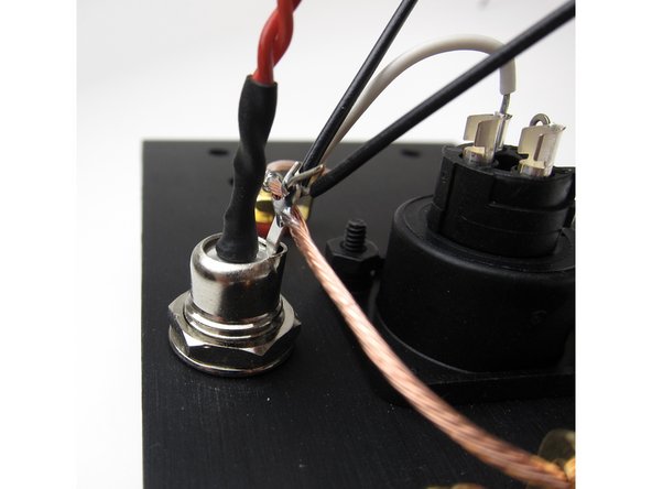
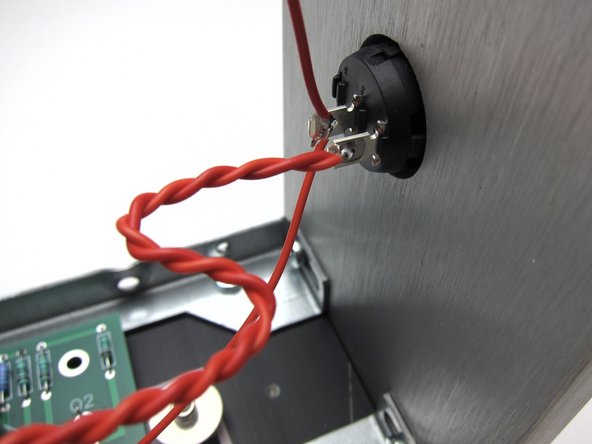
Make a twisted pair from red and attach to the center pin of the barrel connector. This will reach to the front panel switch.
-
Add a bit of heatshrink
-
-
-
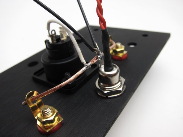
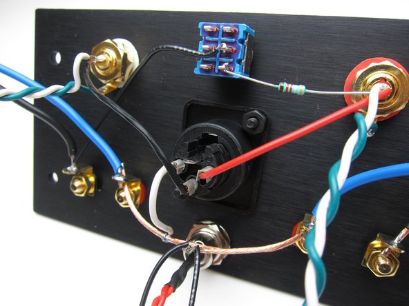
Image 1 - Panel so far.
-
Image 2 & 3 - The rest of the connections, specifically;
-
XLR - Pin 2 is connected via red wire to the red RCA pin. Pin 3 is connected via black wire to the white RCA pin.
-
RCA - make a twisted pair of white and green long enough to reach the PCBs and attach white to the RCA pins and green to the tab.
-
Speaker Posts - using blue wire connect to the red (inboard) posts. Use black wire to connect to the black posts. These wires must be long enough to reach the PCBs. You may solder the speaker wire and the ground buss to the post now.
-
Stereo/Mono switch - black wire from the black speaker post of the white (left) channel to the center pin of the switch. Then connect the 39K resistor from the pin directly below the wire on the switch and insert the resistor lead into the pin of the red (right) channel RCA
-
WATCH THE VIDEO in the next step before proceeding. (It would be on this step but you can't have a step with videos and images together.)
-
-
-
Back panel wiring shown in this video. Please review before and after you proceed.
-
-
-
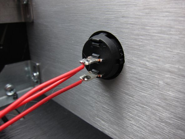
The front power switch is mounted to the panel from the front with the metal terminals in the center and down position.
-
Use your multimeter to verify the switch is functioning correctly before soldering. Be careful not to overheat the tabs during soldering which may melt the switch, in which case you'll need a replacement.
-
The bottom terminal receives power (V+) from the center pin of the barrel connector.
-
NOTE - yes, the wire from the barrel connector should be doubled up and twisted. These are the only photos that show these steps in-progress. :)
-
Image 2 shows the connections to the switch
-
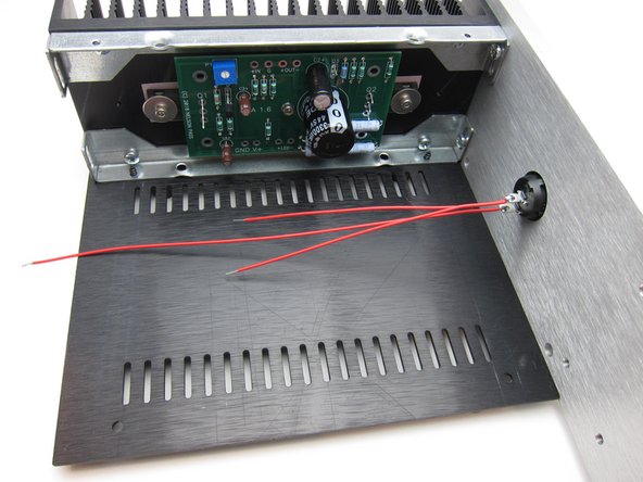
Image 3 shows the connections from the center terminal of the switch to the PCB
-
See video in the next step for overview.
If you’re a Pom an Aussie or a Kiwi you’ll want to turn the switch 180 to the guide photo to get down position as on.
Mike: The ACA was sold in 4 versions - black/silver and a choice of front power switch hole and no front power switch hole. If you didn’t receive what you ordered, please contact support at contact@diyaudiostore.com. For your chassis, please see the step titled “Panel for "No front power switch" build” and also review the wiring diagrams which show how to wire your chassis (which doesn’t have a front power switch hole) together.
-
-
-
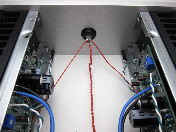
Video with overview of PCB and power wiring.
-
Shown are the connections from the top and bottom edges of the PCB as well as the power switch and barrel connector wiring.
-
-
-
Your kit includes 4 LEDs. Some batches of ACA kits have clear looking LEDs, of which 2 are red and 2 are blue. If this is the case, you will need to test which is which.
-
Do not connect them to DC without a resistor in series. Connecting them directly to your 24V power supply will fry them instantly. Here's 3 methods to safely check the color:
-
(a) Use your multimeter's diode test mode
-
(b) Use a 1k resistor in series with a 9V battery or a 10k resistor in series with your 24V PSU
-
(c) Build your amp up without soldering the LED wires to the PCB, power it up, and try them in the live circuit (which itself has a 10k resistor in it to protect the LED)
-
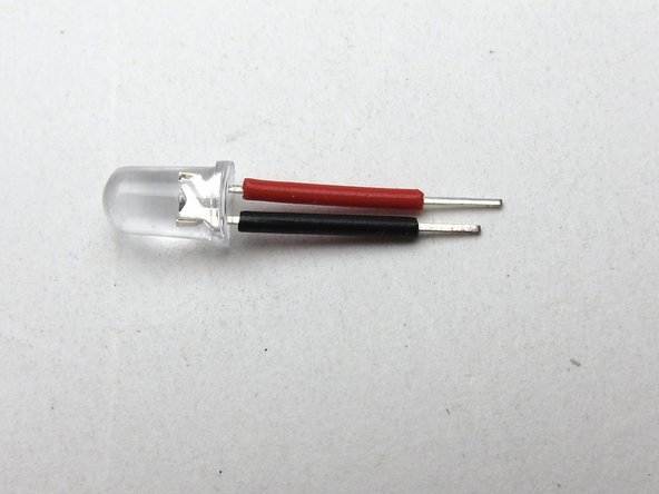
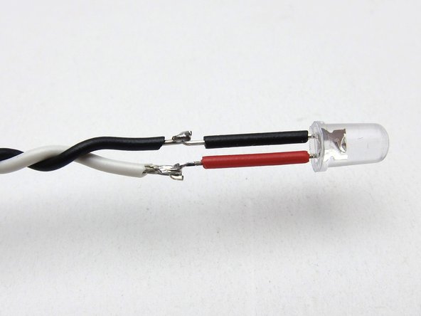
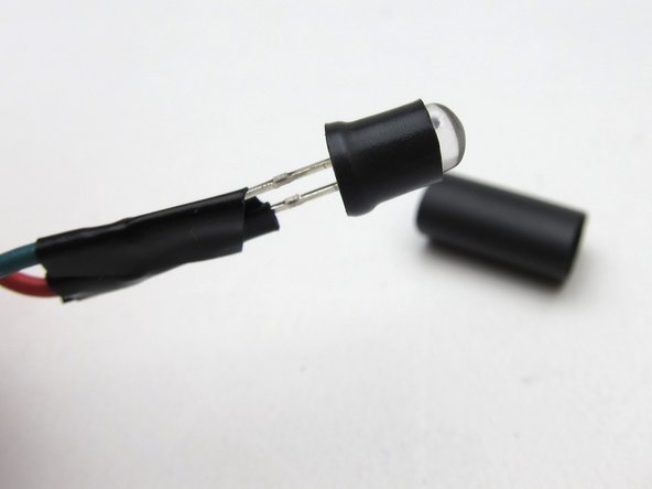
First take some left-over insulation from stripping your other wires and add it to the legs
-
Then attach the wires. Long lead to +ve (shown as white wire), short lead to -ve (shown as black wire).
-
Tip: Cut the short lead and its insulation even shorter. That way the exposed part of the leads aren't opposite each other and can never touch.
I agree with the remark about cutting the short lead shorter so joints are staggered and can’t short, but this is not reflected in the photo.
Hi, step 41 text says “white wire” but photo shows red insulating sleeve (on 06 Sept 2018)
-
-
-
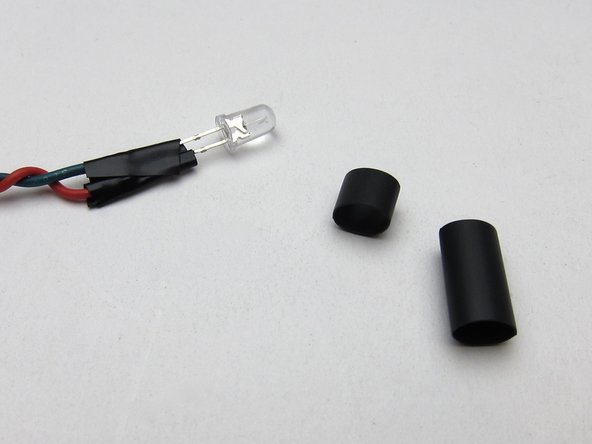
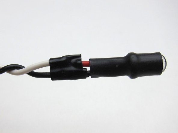
Your kit includes heatshrink that is pliable when warm and should nicely seat the LED in the hole in the front panel.
-
We have discovered there can be quite some variability in the thickness (and malleability) of the heatshrink used between batches. Use 1 or 2 layers as you feel works best for you.
-
Take an inch and cover the leads, flange, and half the body.
-
So that it stays in place, you may need to use some insulation or similar malleable material to create a shim. Optionally, heatshrink another 3mm piece on the head of the LED (some builders have reported this makes it too thick to insert).
-
You may need to use a little creative "DIY" here. Do what works best for you.
FWIW blue LEDs usually require a slightly higher voltage to “fire”, I bet they were fine. I used a 9v battery w/the 39K resistor (for the back panel switch) to test mine, AOK. Bet your diode check function puts out <3 volts. Off topic FWIW2 testing microwave HV diodes (multi-junction) also requires an additional external series trigger voltage, again I use a 9v battery in series w/my meter.
My V1.8 came with two reds and two blues. Using my multi-meter's diode test mode the red ones lit up fine, but not the blue. So I used the blues as test dummies for various mounting ideas, trying heatshrink, etc. Heatshrink is not meant for this purpose. I tried a bit of Joe’s Sticky Stuff- messy. I did heatshrink the soldered connections, but not the LEDs.
I had a couple of inches of doubled lead to spare, so I used the twisted lead’s natural springiness to push the LEDs into the hole, where they seem to want stay put. I may add just a drop of silicone to discourage them from coming out.
My heat shrink around my LED just bunches up into a thick mess when I try the method above. One layer of heatshrink (instead of two) and a tiny dab of super glue work wonders. I must be doing something wrong.
Evan is correct, using two layers of heat-shrink does not work, it is too thick. A single layer on the base of the LED near the flange works fine.
Puma Cat -
-
-
-
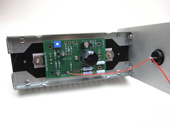
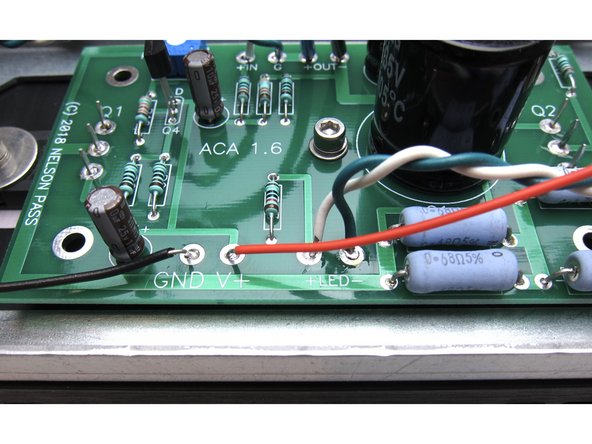
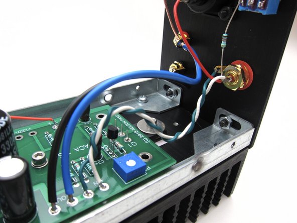
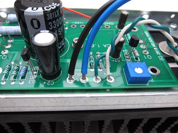
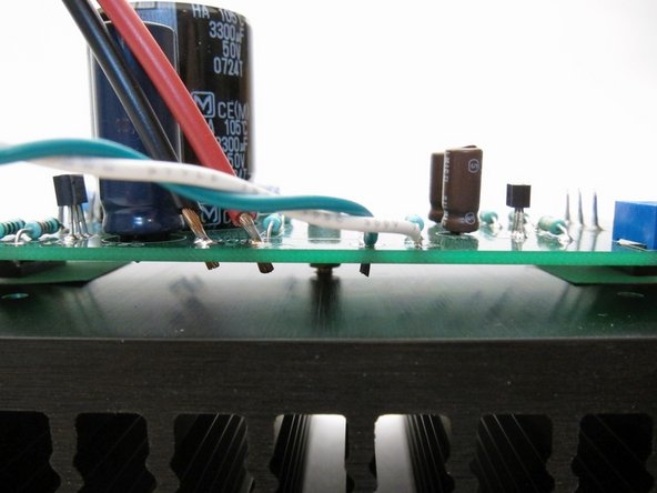
In the first photo you can see the power connections from the circuit board power and LED on the bottom edge,
-
Photo 2 and 3 show input (from RCA) and wiring to speaker posts on the top edge.
-
-
-
Since many wire connections need to be soldered from the top of the PCB, strip the insulation and trim so it sticks through only 1-2mm. Make sure it does not touch the heatsink!
Might be more trouble than it’s worth, but when I did this , after stripping the wires, I fit the wires into the PCB holes and to see which direction they were pulling out. I think put a very small 90 bend on the end of the wire to catch on the PCB board instead of popping out. This allowed me to solder more easily & also helped to ensure the wire didn’t contact the heat sink.
-
-
-
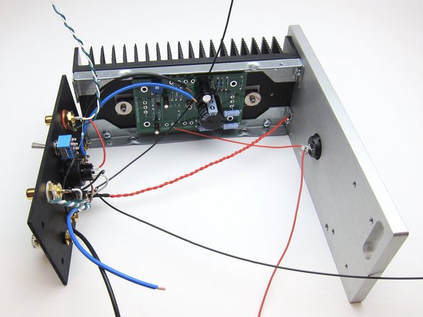
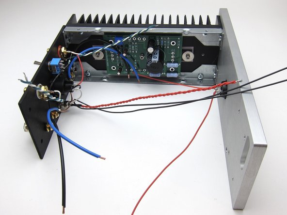
With the previous steps completed it's now time to start bolting it all together.
-
Mechanically, start with one of the PCB/heatsink assemblies and attach to the front panel. Then secure the back panel to the same heatsink assembly.
-
In this configuration try to get as many connections completed as possible, it will get more difficult when the 2nd heatsink is attached.
-
If you have a wire that's too long, you can trim or put a bend or two into it to take up the slack. This will also act as a stress relief on the wire and solder connection.
-
-
-
Final wiring should look like these photos.
-
-
-
This video shows the wiring of the completed amp
-
-
-
Video covering power up, connections and normal operations. Only one speaker shown because I can't fit two on my table.
-
The quiet turn-on noise is heard, as well as the small turn-off thump. This is expected behaviour from this particular minimalist circuit design. If you're really interested, there's a good thread about this topic brewing here.
-
Music used - Jan Johansson - Visa från Utanmyra https://www.youtube.com/watch?v=t2D5HlKL...
-
-
-
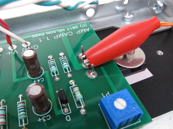
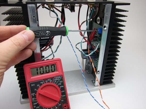
Setting the DC balance is very easy and the same for the 1.6 and 1.1
-
First image: Connect your DMM red lead to pin 2 of Q1
-
Second image: And the DMM black lead to ground. The buss is a perfectly good place to attach.
-
Buying clip leads for your DMM is not necessary for this job, but it does make many tasks much easier. :)
-
-
-
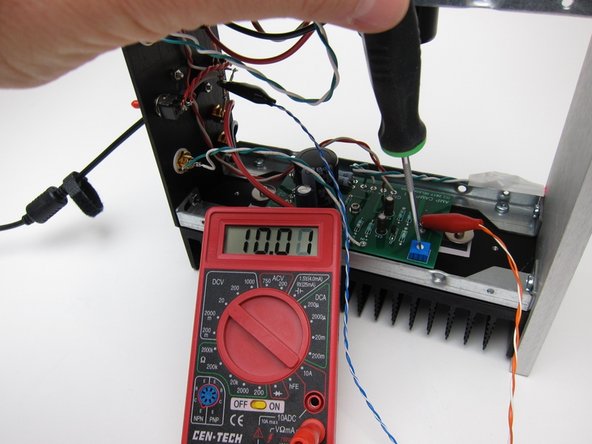
Set your meter to DC volts, use the 20vdc range if your meter is not auto-ranging. If using 24v PSU, set meter to 200vdc.
-
If using 19v PSU Adjust the pot in small steps to get 10v. A few tenths off in either direction is nothing to worry about. If you are using the 24V power supply, adjust the pot to get 12V.
-
The changes in voltage will lag behind the pot movement, almost in slow motion - this is normal. Small steps, wait a bit to let the voltage catch up, adjust a bit more, wait, etc...
-
You don't need to remove both the top and the bottom panels to make adjustments, however it's super easy to get to everything if you do.
-
-
-
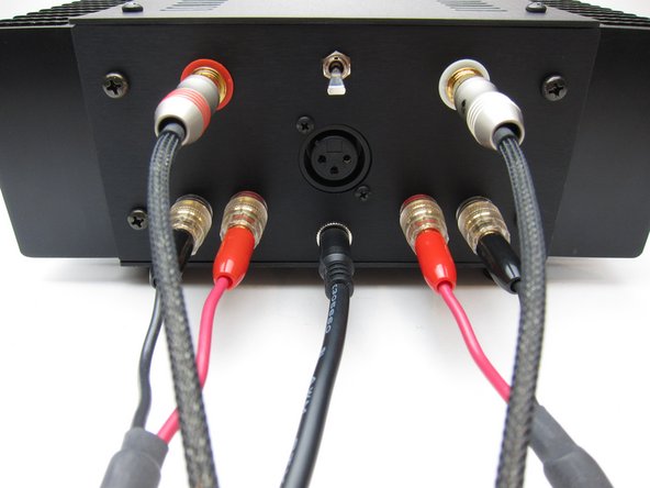
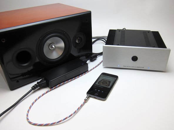
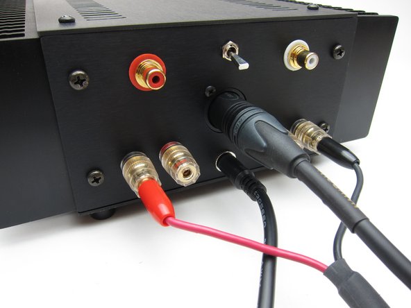
The ACA 1.6 is a fantastic stereo amplifier. Connections for proper use are as follows;
-
RCA inputs - Connect your source (Preamp, Phone. DAC, CD player with variable outputs, etc...) to the RCA jacks.
-
Stereo/Mono switch - should be DOWN for Stereo operation.
-
Speakers - Connect your speakers to the speaker posts as shown
-
Power - The PSU must be attached to the barrel connector and plugged in.
-
-
-
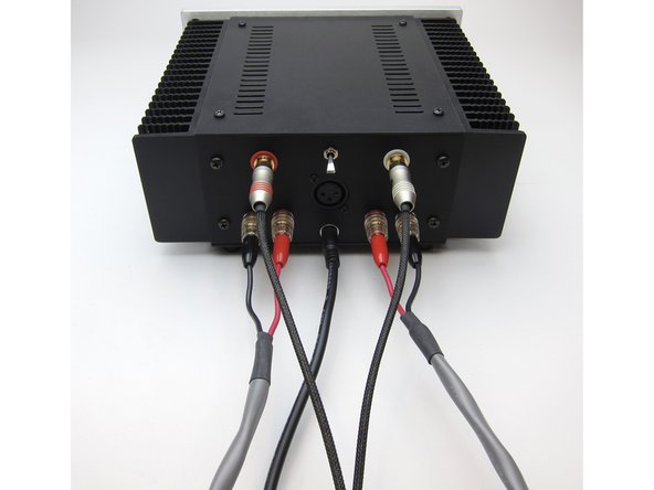
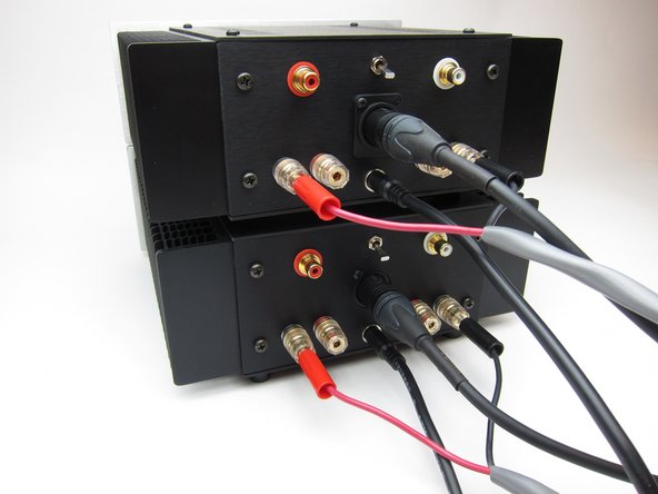
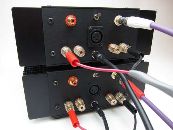
If using a source that has XLR cables, plug the XLR into the jack, and wire the speakers as shown.
-
Stereo/Mono switch in the DOWN position. (That switch is only used for RCA input)
-
Regardless of how you wire for bridged operation, you'll need two ACAs for stereo now.
-
Please see the ACA Operation Modes document for more information about stereo, balanced, bridged and parallel operation.
I am preparing a 1.8 build and I noticed that the bridged XLR speaker wiring is different between 1.6 and 1.8 build guides.
In both guides red RCA + is connected to XLR pin 2 (hot/positive) and white RCA + is connected to XLR pin 3 (cold/negative), which means the ‘red side’ amp is processing + signal and ‘white side’ amp is processing - signal.
In the v1.8 guide speakers are connected - to ‘red side’ and + to ‘white side’, which seems correct to me and is in alignment with the v1.8 chassis back panel drawings.
But in this 1.6 guide it is the other way around: speaker - to ‘white side’ and speaker + to ‘red side’
If I am understanding the working of this amp correctly, the 1.8 guide is correct and this one is wrong.
Or am I misunderstanding something completely?
-
-
-
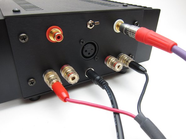
RCA input mono operation;
-
Connect RCA input to the white RCA.
-
Stereo/Mono switch in the UP position.
-
Connect speakers as shown.
-
-
-
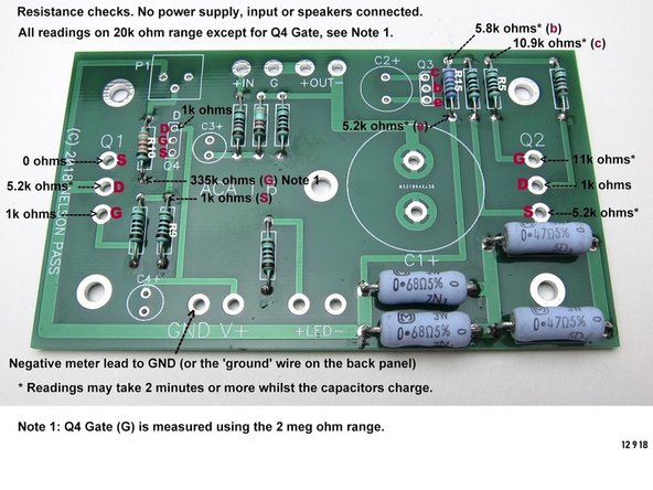
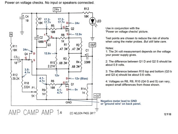
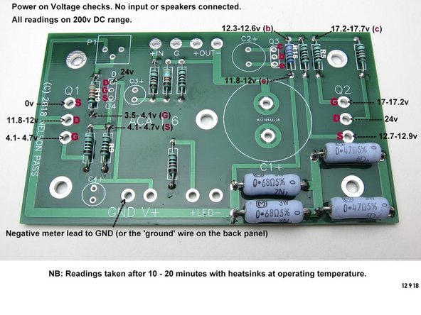
These annotated photos and schematic have some simple checks you can do with your Multimeter in case you have issues with your build.
-
Please note, most people having issues have found it to be some combination of soldering - a bad or cold joint, no solder, or a solder bridge.
-
That said, check all components to be in the proper location, make sure things are wired correctly, and make sure all components are installed.
-
More troubleshooting insights... etc etc, look at the notes on the images for more info until this section can be fleshed out.
-
-
-
Discuss your build and ask for help about anything at all in the ACA 1.6 Build Guide Thread
-
Upload photos of your finished product and talk about everything else in the Amp Camp Amp General Discussion Thread
I just completed building 2 ACA amps for use with my Pass DIY passive Pre and my Pass 6-24 biamp analog crossover. This system will be used to drive my full range speaker built after the PAP Duet 15 product. To start my comments let me say that each of these DIY products are. Result of the genius of Nelson Pass. He willingness to support DIYers is really appreciated.
The kits themselves have high quality PCBs and are well documented. The packaging is also well done and help avoid damage in transit. The build guide that 6L6 developed is so,well done and IF followed correctly creates a very successful build.
I built my first stereo amp Knight Kit at. 13 years old. Now at 75 I have rediscovered the joy of DIYing. I own a much more expensive audio system but I must say I enjoy the PASS designed products more.
-


We hope you enjoyed the guide! Please discuss your build, ask for help, upload photos and generally join in the diyAudio community discussion threads listed above!
We hope you enjoyed the guide! Please discuss your build, ask for help, upload photos and generally join in the diyAudio community discussion threads listed above!
Cancel: I did not complete this guide.
30 other people completed this guide.
My “stubby” Phillips screwdriver was very useful in making final fitment adjustments to the heat sink brackets and case.
OldJSD91 - Reply
BoM follow on post. Refer the ACA Thread - Post #8626 for details.
astromo - Reply
The P1 is not in the component list..
Neel007 - Reply
One more suggestion, if you haven’t already invested or thought about wire strippers, I think these units are “GOLD”:
https://www.irwin.com/tools/pliers-adjus...
You can strip a wire one handed and they can get into some pretty awkward spots. I was thanking the wisdom of that purchase and got a full return on investment over the course of the ACA build. One to consider. There may be other ways to skin the cat but this worked for me.
astromo - Reply
Refer here for the original BoM:
[|https://www.diyaudio.com/media/files/art...]
*face palm* it was there all the time! … just got to know where to look or … in other words (and note to self) - RTFM
Here’s the full story:
[|https://www.diyaudio.com/forums/diyaudio...]
astromo - Reply
Thanks for your suggestions. Eye protection is a great idea, we’ll add that. Please see our solder information page for details about fume extractors and leaded solder safety. We’ll try to make this information more visible in the guide.
Jason - Reply
Not a comment for the schematic but for the Introduction.
It wouldn’t hurt to provide cautionary advice for builders to think about eye protection before they start soldering &/or cutting leads.
You can go over board with safety precaution info … gee, soldering irons get hot so don’t touch that stuff - pretty obvious. However, you just never know where that cut lead will spin off to. You get the idea.
Mentioning a solder fume extractor wouldn’t be a bad idea either, especially for those using lead solder.
astromo - Reply