Reputation over time
It looks like this user hasn't gained any reputation yet.
Once they have, you'll be able to view a graph of their reputation gained over time.
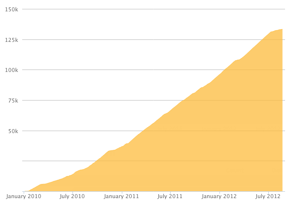
Here's a preview of what the graph will look like:
Reputation Breakdown
No reputation gained yet.
291
There’s a resistor in the set that does not get installed on the PCB board and is not on the ACA 1.6 component values list . Don’t lose it, this will be used on the back panel.
Note that several of the solder points on the back panel will have more than one connection soldered on (e.g. the red RCA jack will have a resistor, the right channel PCB board, and XLR pin 2 all connecting to the same point). I wish I would have waited to solder this connection until I had all of those connection ready to go. Soldering them in after something else was already soldered there was a PITA.
Wonderful guide, helped me get it right the first time! Thank you for your time in putting this together.
Note that the PCB boards on each side will mirror each other, so don’t cut all wires to length based on the first PCB board you solder up.
Might be more trouble than it’s worth, but when I did this , after stripping the wires, I fit the wires into the PCB holes and to see which direction they were pulling out. I think put a very small 90 bend on the end of the wire to catch on the PCB board instead of popping out. This allowed me to solder more easily & also helped to ensure the wire didn’t contact the heat sink.
In my kit one of the wire colors contains both a single conductor and a stranded conductor. I used the stranded conductor to connect to the board and the single conductor for the power switch. I’m not sure what is right or if it matters.
Clamping the wires you want to make a twist out of into the jaws of a drill chuck is a great way to get a beautiful and tight twist in all of your wires.
I believe all of these chassis assembly instructions are out of order. They should follow assembling/soldering the back-panel.
Suggested order (my very first amp build, so take this and all of my other comments with a grain of salt:
1: Stuff and solder PCBs
2: Fix Q1/Q2 to heatsink
3: Mount PCBs & check for shorts to sink
4: Stuff and wire back panel
5: Attach rails to heat sinks
6: Attach one heatsink to back panel and face plate (P1 pot toward top)
7: Wire back/front panel --> PCB
8: Attach second heatsink to back panel and face plate (P1 pot toward top)
9: Wire back/front panel --> PCB
10: Power up & set bias
11: Attach ventilated top/bottom covers
The main photograph for this is somewhat out of order. It shows the chassis rails screwed on, but you will not be able to check your work in Step 17 if you attach the chassis rails at this point.
Mine also came with plastic.
Page 1 of 2
Next