Introduction
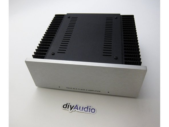
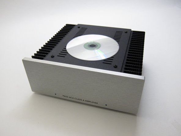
'This build guide is for all builders of the Amp Camp Amp V1.5 kit that was sold in March 2018 from the diyAudio store.
How do you work out if you have V1.5? We didn't do so great on consistent version numbers. You have V1.5 if (a) your PCB says V1.1 on it and has one single central PCB mounting hole and/or (b) Your kit was purchased in March 2018 from the store and your SKU contained the string "V15". Starting with V1.6 the kit, the PCB and the chassis will all share the same version number :)
If you have a V1.6 kit, you'll be after the ACA V1.6 Build Guide.
-
-
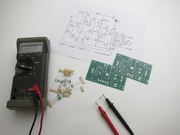
Print this out on paper and have it in front of you during the whole process.
-
-
-
One bag should contain the resistors, pots, capacitors
-
One bag should contain the PCBs and Keratherm insulators
-
The Silver Mylar bag (not photographed) contains the Mosfets , Jfets and small transistors.
-
-
-
Measure EVERYTHING before placing in the board :)
-
Have the schematic printed in front of you at all times
-
-
-
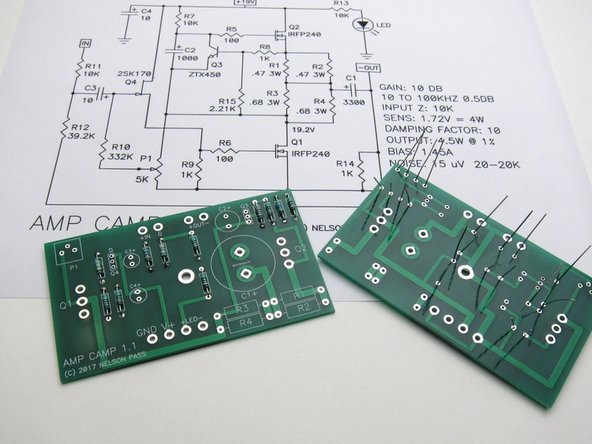
Generally it's easiest to start stuffing the PCBs with the smallest components first - in this case the resistors.
-
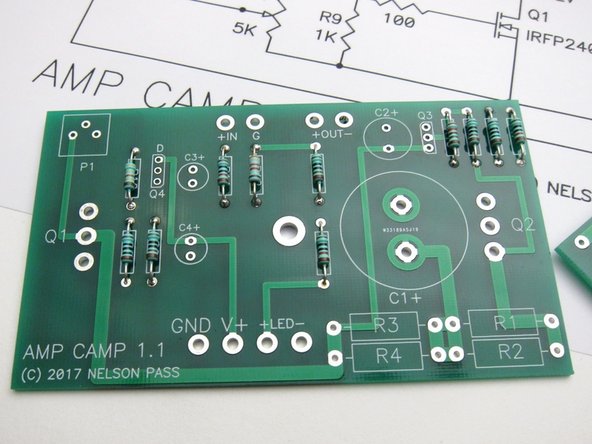
Note the 1% resistors all have a brown band at one end - to help assist troubleshooting in the future if needed, place the brown at the bottom of all resistors.
-
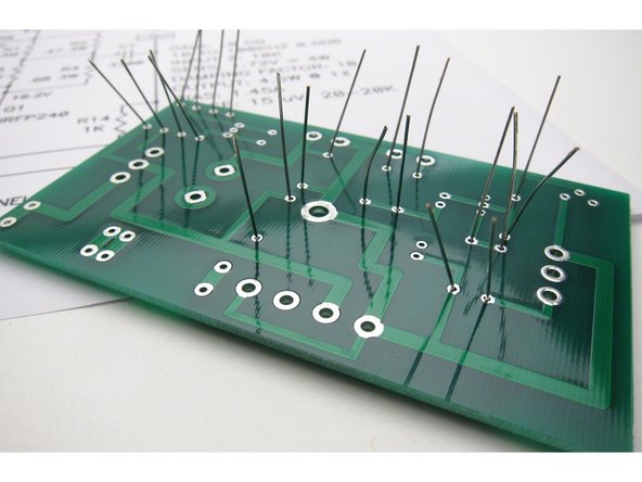
Slightly bend out leads before soldering
-
-
-
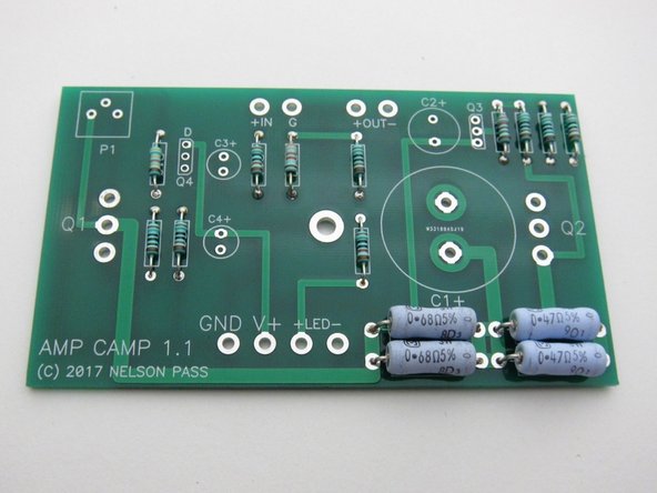
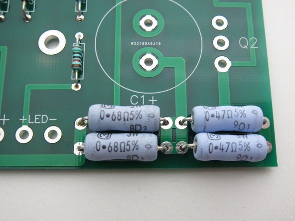
The big and little resistors in their places. Note the large resistors have the value printed right on them - try to bend the leads so the values show and align as shown.
-
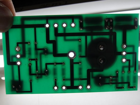
If you hold the PCB up to the light, you can see if you missed any solder holes
-
Arrange resistors with values showing
-
-
-
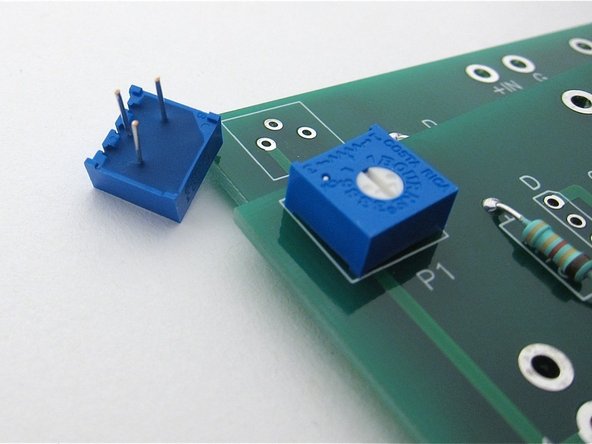
The potentiometers have three leads in a triangular formation, they are impossible to insert backwards.
-
-
-
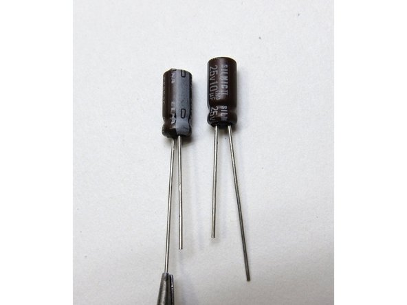
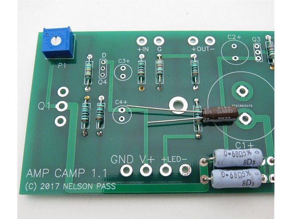
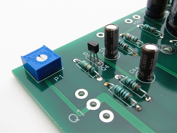
Capacitors have polarity - the long leg is Positive +, and the mark on the can shows negative -
-
Second image shows: Long leg in the positive marked hole
-
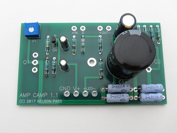
Third image shows: Everything on PCB except the big power transistors.
-
-
-
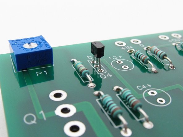
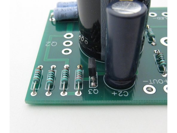
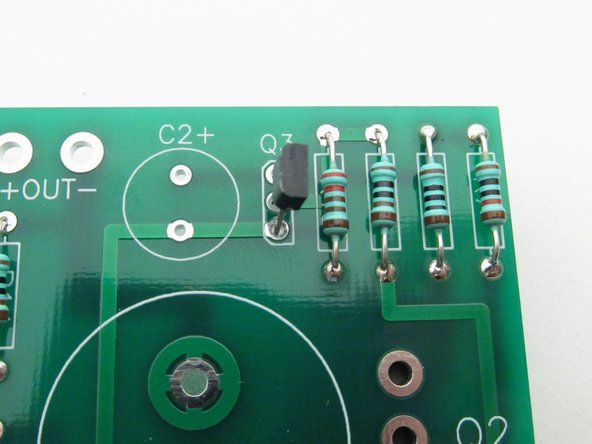
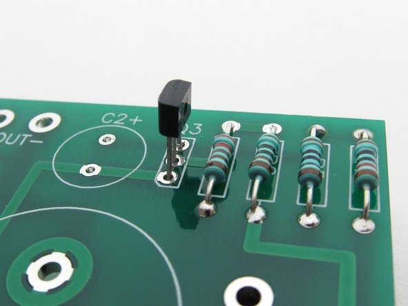
Align the flat of the small transistors with the silkscreen as shown.
-
Q4 is the input Toshiba or LS Jfet, marked K370 or K170 on the flat of the package.
-
Place Q4
-
-
-
Place Q3
-
-
-
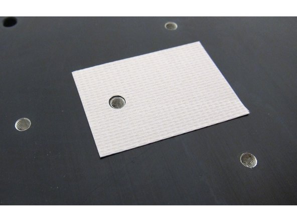
Keratherm is a great modern replacement for the (sometimes toxic and always messy) thermally conducting goop required to attach transistors to heatsinks
-
The Keratherm insulator is the thinner rubbery pink stuff. The brown material (not shown) is just the backing.
-
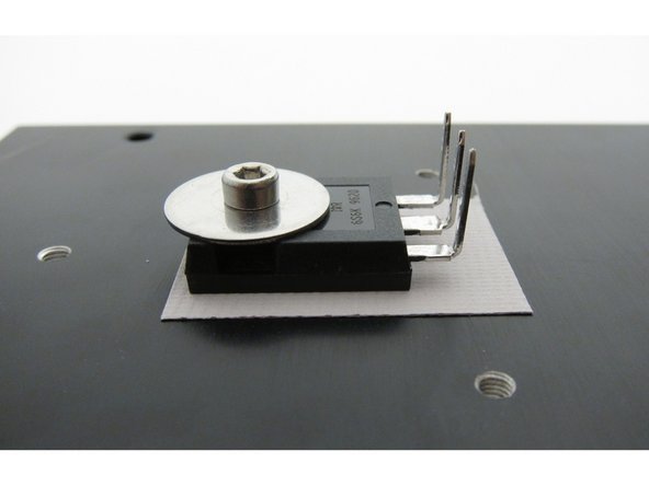
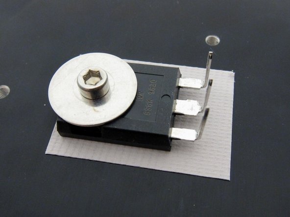
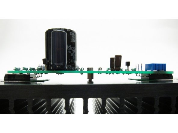
Big transistors mount as shown here, and gently bend the legs up right at the point that they narrow.
-
There should be a lock washer (split washer, spring washer) between the fender washer and the screws. I will correct the photos in the near future.
-
-
-
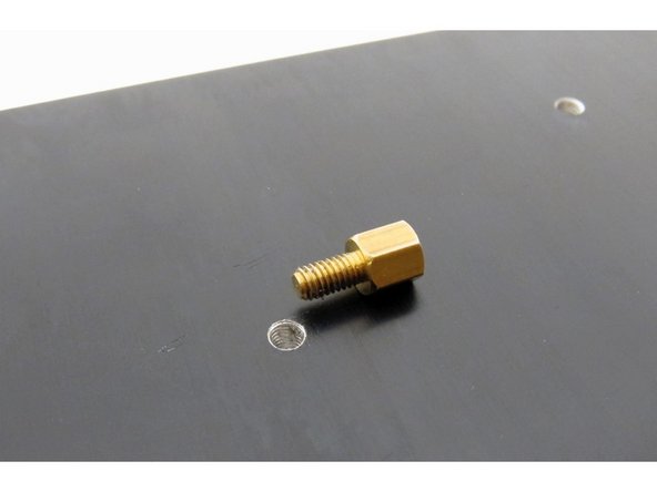
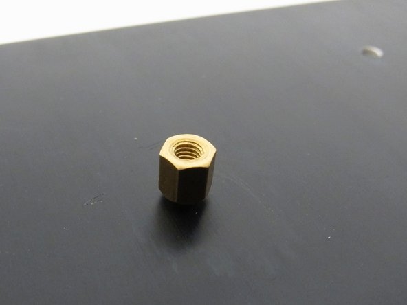
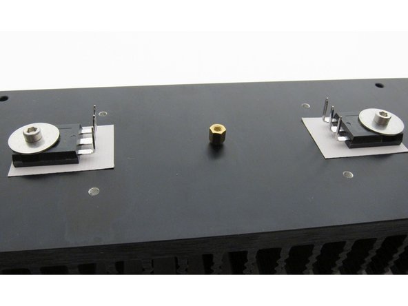
Before mounting circuit board, attach one brass standoff to the heatsink. Do not over-tighten!
-
It does not have to insert all the way flush into the heatsink.
-
-
-
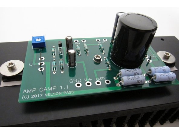
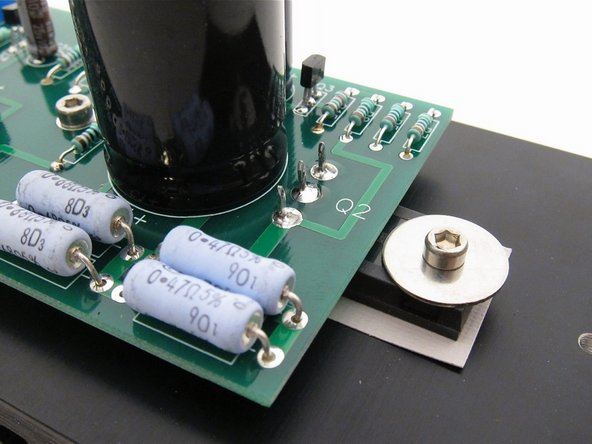
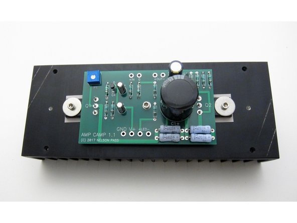
One screw and washer to hold the PCB to the center standoff, and align the big transistor legs with the holes.
-
Solder the transistors.
-
-
-
Sit back and take some time to admire the work you've done to date
-
Check that under the PCB there are no leads touching the heatsink (which is grounded)
-
-
-
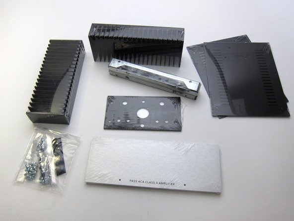
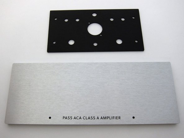
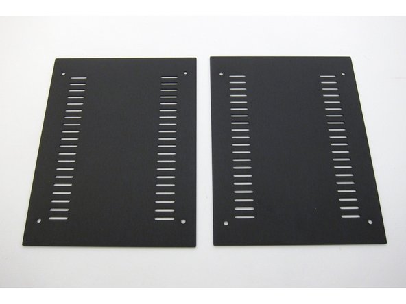
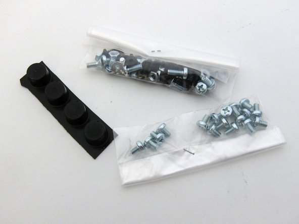
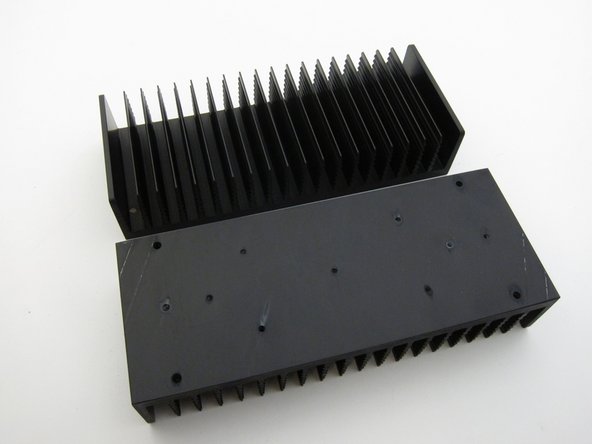
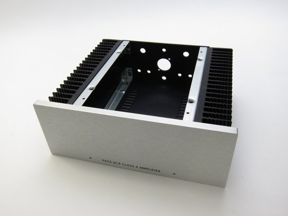
Check you have all the bits
-
First image: Chassis contents
-
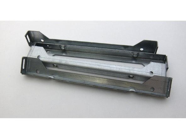
Second image: Heatsink rails
-
Third image: Front and rear panels
-
-
-
First image: Ventilated top and bottom panels
-
Second image: Hardware
-
Third image: Heatsinks
-
-
-
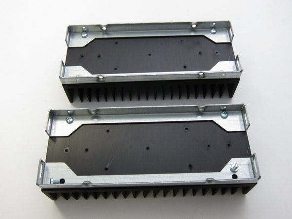
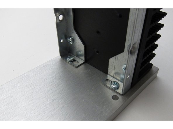
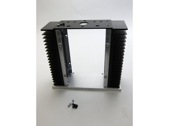
Attach the rails to the heatsinks
-
-
-
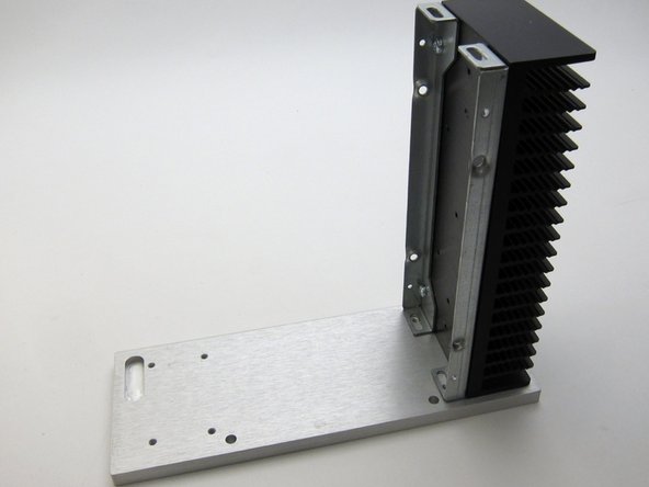
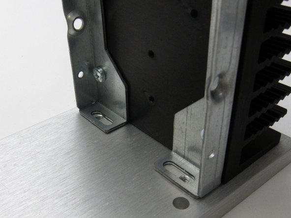
First image: Align slots with the holes in the front panel
-
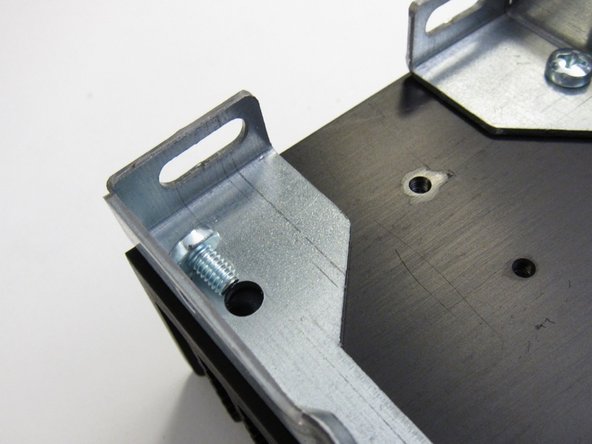
Third image: Screws insert as shown
-
Please note that there is some intended slop in the bracket attachments. This can create slight alignment errors later when you are putting together the finishing touches on the chassis like screwing in the covers.
-
You might need to just tighten these up "fit tight" so you can wiggle them later, when you do a final alignment to get the screw holes in the covers to line up.
-
-
-
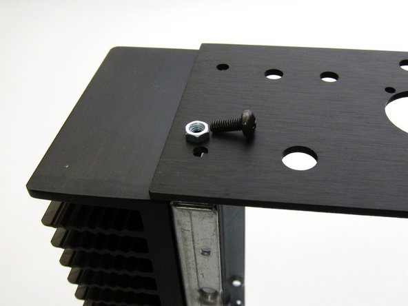
Rear panel attaches with nut and screw
-
-
-
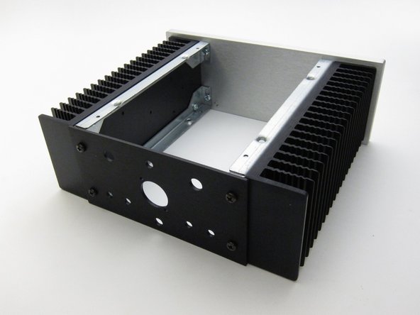
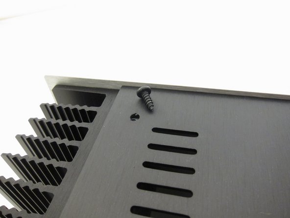
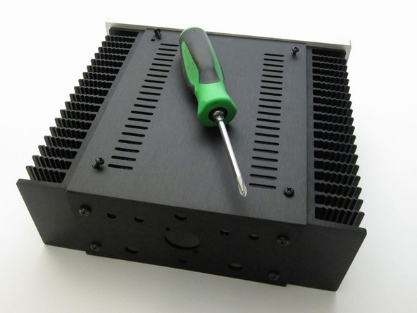
Sheet metal screws attach the top and bottom panels
-
-
-
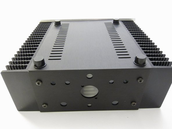
Feet are stick-on
-
-
-
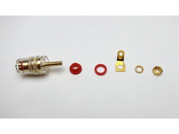
Back panel hardware
-
Third image: Speaker binding post hardware
-
-
-
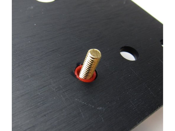
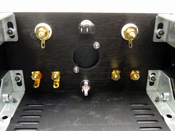
Viewing from the inside of the amplifier
-
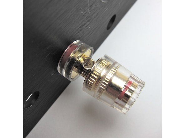
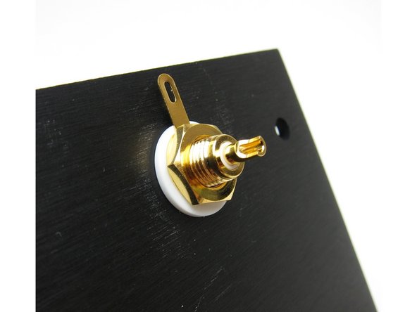
First image: The colored shoulder washer goes on the outside, through the hole. This is to align the post so that no metal touches the chassis.
-
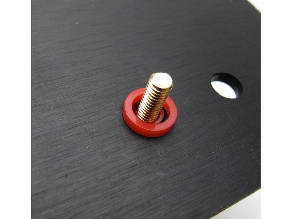
Second image: Then the other plastic washer
-
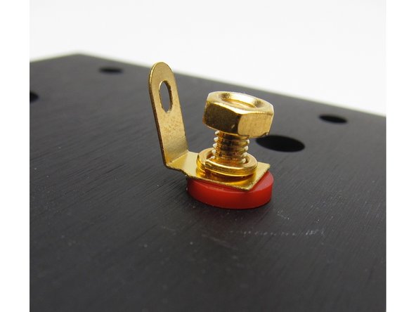
Third image: The metal tab sits upon the plastic, then lockwasher, and nut
-
-
-
Align the hole in the post to be vertical.
-
-
-
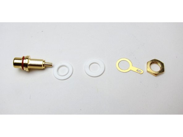
First image: RCA post hardware
-
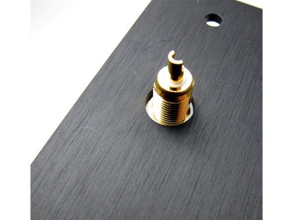
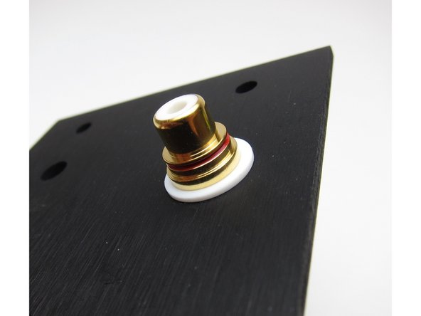
Second image: Again, viewing from the inside, the shoulder washer sits in the hole and keeps the metal of the RCA from touching the chassis
-
-
-
Interior view
-
-
-
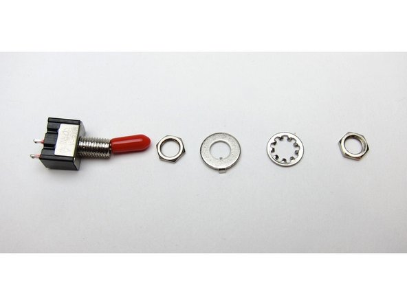
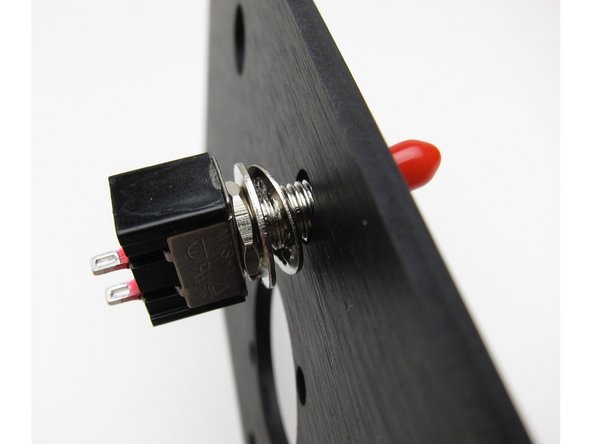
First image: Note that the big washer has a key to fit in the switch groove, and a bent tab. Point that tab towards the body of the switch, not the chassis
-
Second image: Star washer on the inside touching the chassis
-
When you add the first nut make sure it's adjusted all the way back
-
Use a miniature spanner, wrench or socket to tighten the last nut
-
-
-
First image: Power check (external view)
-
Second image: Lockwasher and nut on the outside of the chassis
-
Third image: Align so the longest tab is up
-
-
-
Second image: Please note that this photo shows the speaker posts reversed - place the red speaker posts inboard of the black.
-
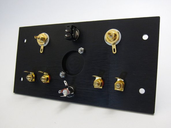
Third image: This photo shows some small errors - Please place the Red speaker posts inboard of the black and rotate the switch 90deg so the terminals are on the bottom and center. Later photos will show why.
-
-
-
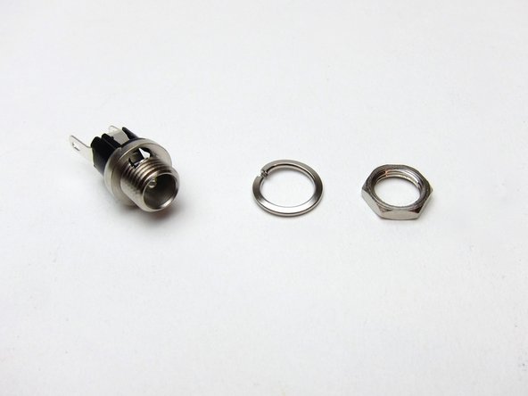
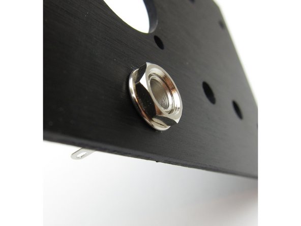
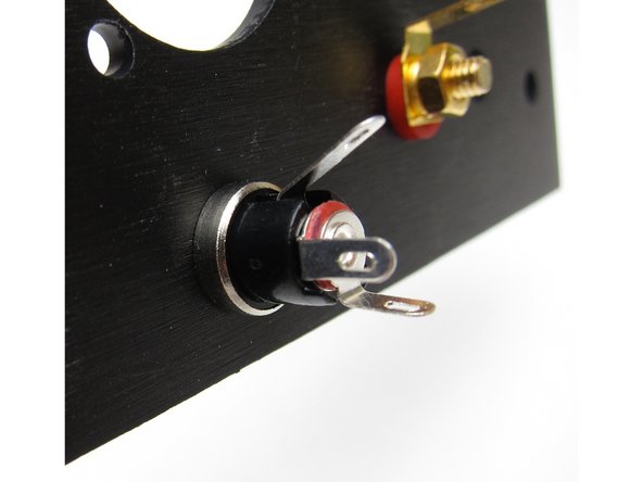
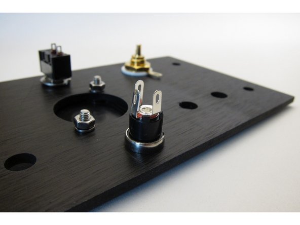
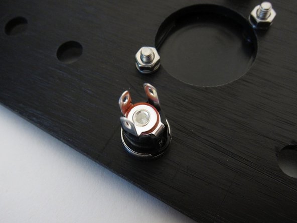
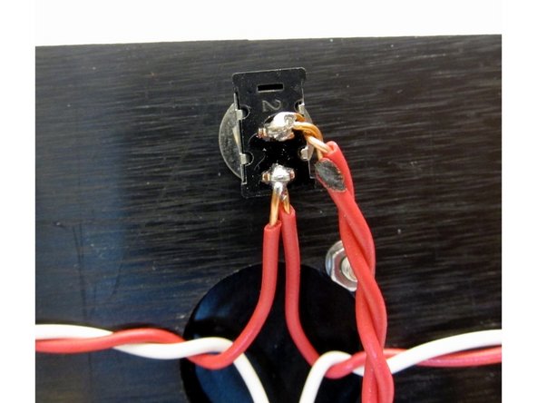
The solder lugs of the PSU barrel connector are all different lengths. Attach so the longest one is up.
-
The tab that connects to the center (the bottom tab, in this photo) is the PSU's pin connection.
-
-
-
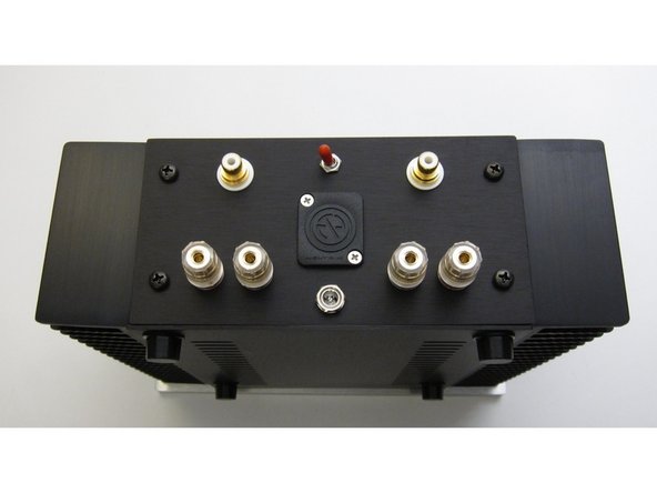
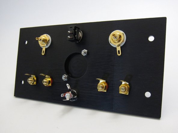
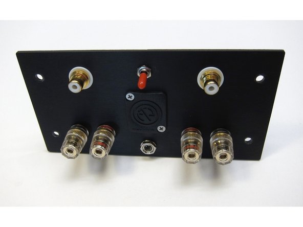
This photo shown the proper configuration of the jacks and switch. Red inboard, black outboard, switch alignment where up will be on.
-
-
-
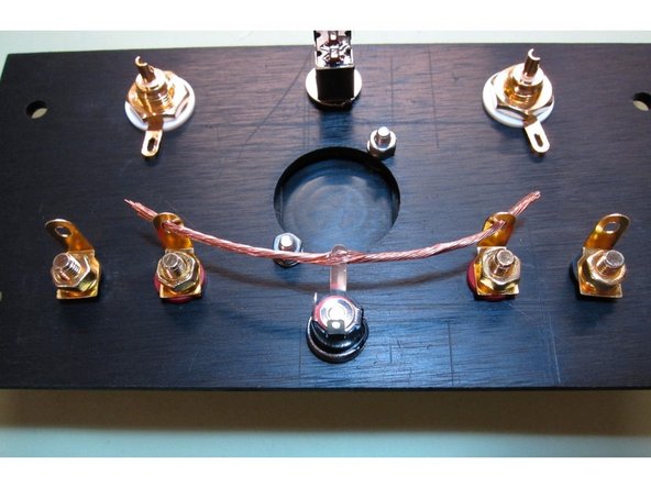
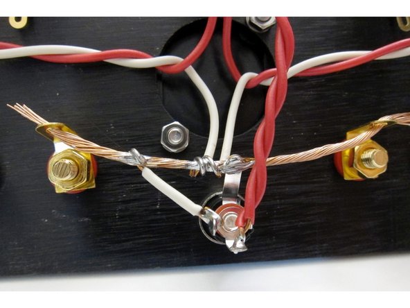
Take some of the heavier wire included in the kit and cut a length as shown in the picture. Strip off the insulation so the wire is bare.
-
The bare wire will make a ground buss for the entire amplifier. Do not solder the wire to the speaker jacks yet.
-
-
-
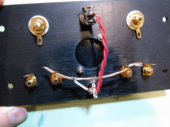
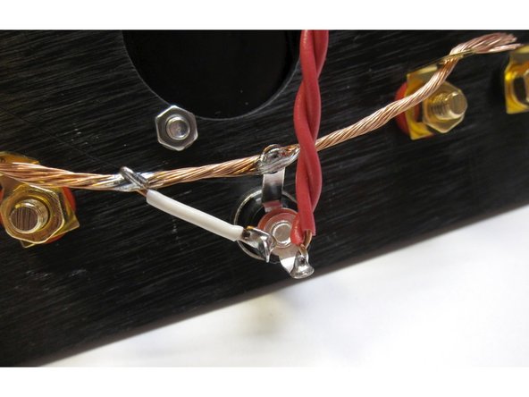
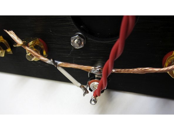
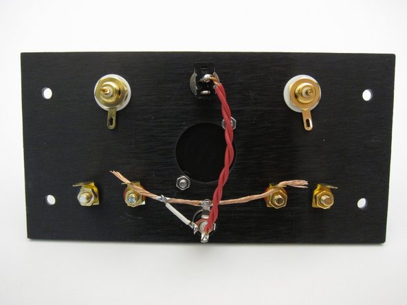
Second image: In this photo you can see that the top tab of the barrel is soldered to the buss wire. The outside connector of the barrel (PSU ground voltage) is connected to the the buss via the small white wire. PSU + voltage from the power brick is connected from the barrel pin to the center of the switch via the red wire...
-
(continued)... It's doubled up as both channels are fed from this connection.
-
Third image: Be sure wires and solder connections do not touch
-
-
-
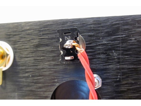
Power to the switch. Again, be careful to trim and clean up any wire after it's soldered.
-
-
-
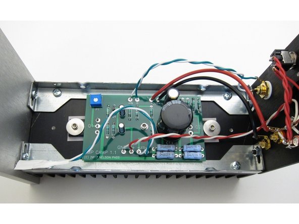
First image: The red and white wires connect to GND and V+ on the Circuit Board. Red is V+, White is GND
-
Second image: Whoops, the soldering iron touched the insulation...
-
Third image: Connection detail.
-
Note: Again, at this time do not solder the ground buss wire to the speaker posts. (They will be soldered later.)
-
-
-
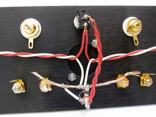
In this photo you can see the power connections from the circuit board to the switch.
-
-
-
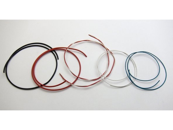
Supplied wire
-
-
-
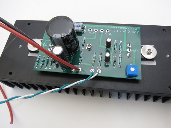
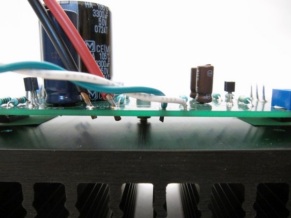
Use some of the red (+) and black (-) wire for the speaker outputs, and twist the green (-) and white (+) together for the input.
-
Strip the insulation and trim so it sticks through about 1-2mm. Make sure it does not touch the heatsink!
-
-
-
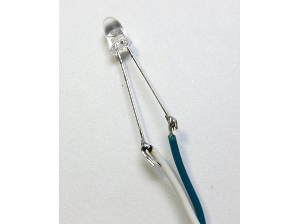
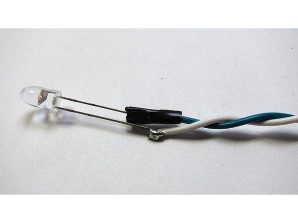
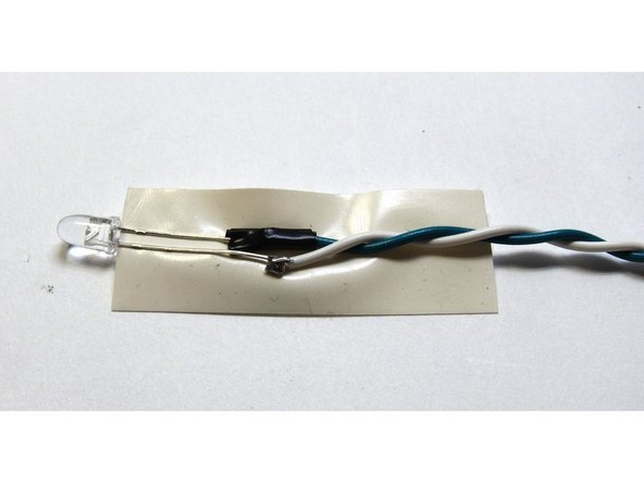
The LED wiring is next. Green (-) and white (+)
-
Long lead to white, short lead to green
-
A bit of tape on one on the solder joints
-
Then tape as shown
-
This is to keep the leads of the LED from touching each other, or shorting out to the chassis itself
-
-
-
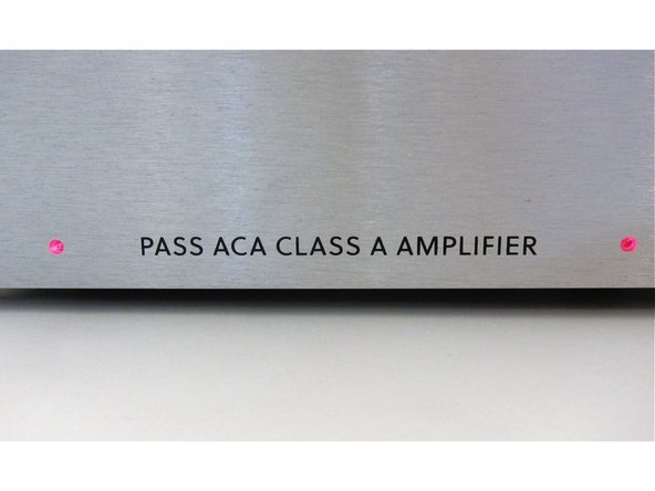
The LEDs are routed forward and placed in the front panel hole - the wire stiffness will keep them in place, particularly if you make the wire a little longer than necessary.
-
-
-
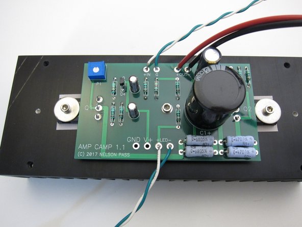
First image: PCB to back panel wiring. Power from the back panel, red (+), white (-)
-
Second image: Input wiring shown - white (+) is RCA jack center pin, green (-) is RCA tab
-
Third image: Now you may solder the ground buss to the speaker post.
-
-
-
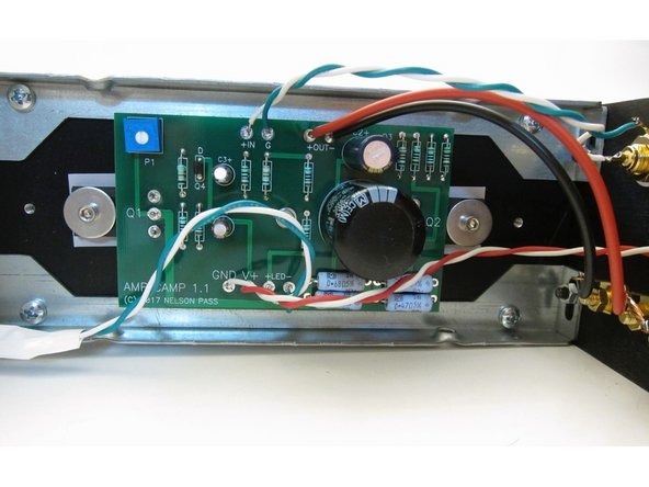
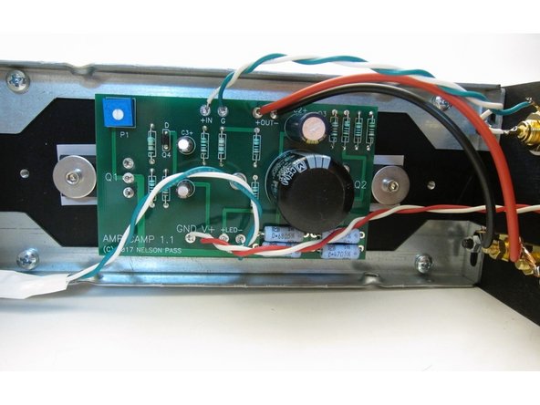
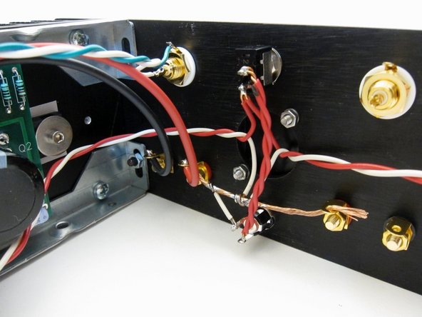
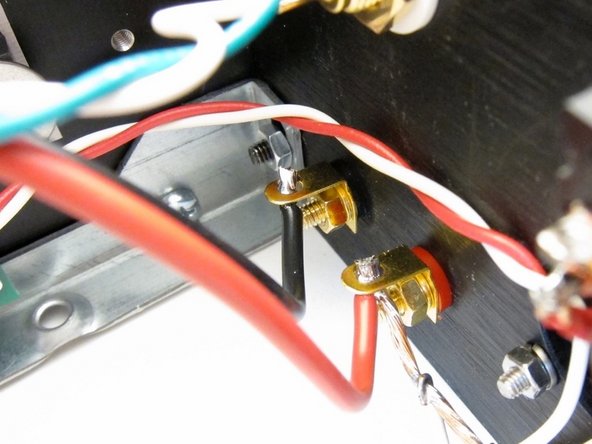
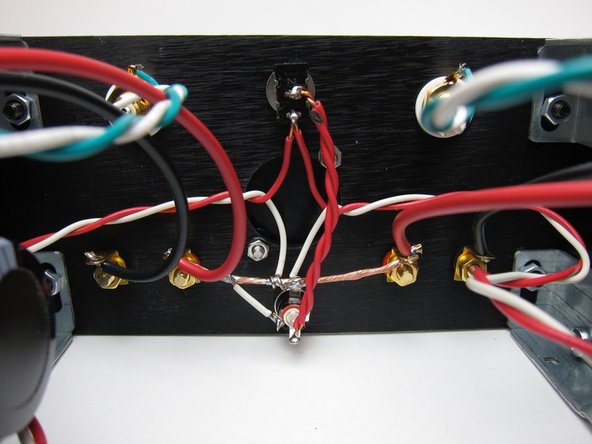
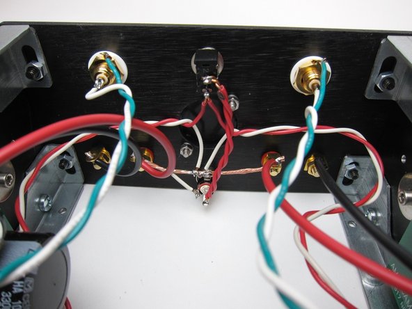
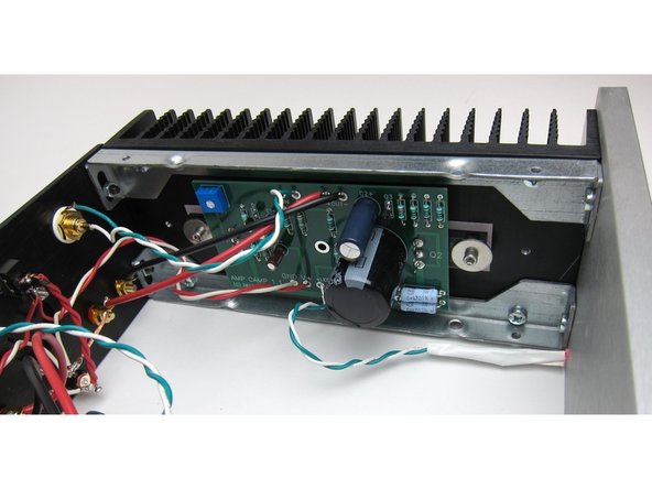
Check everything looks like this!
-
-
-
Setting the bias is very easy
-
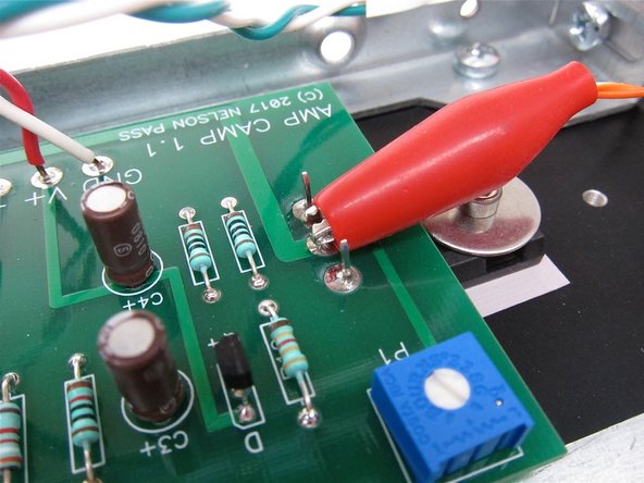
First image: Connect your DMM red lead to pin 2 of Q1
-
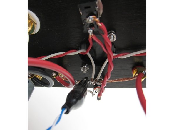
Second image: And the DMM black lead to ground. The buss is a perfectly good place to attach.
-
-
-
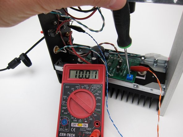
Set your meter to DC volts
-
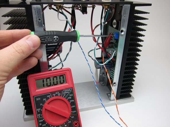
For the ACA1.5 Adjust the pot in small steps to get 10v. A few tenths off in either direction is nothing to worry about.
-
The changes in voltage will lag behind the pot movement, almost in slow motion - this is normal. Small steps, wait a bit to let the voltage catch up, adjust a bit more, wait, etc...
-
You don't need to remove both the top and the bottom panels to make adjustments, but it's super easy to get to everything if you do.
-
-
-
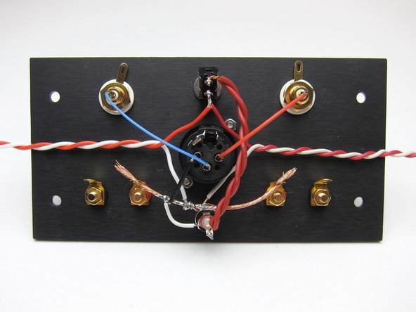
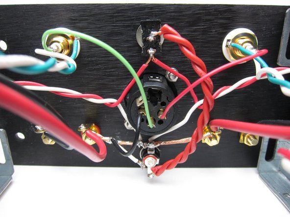
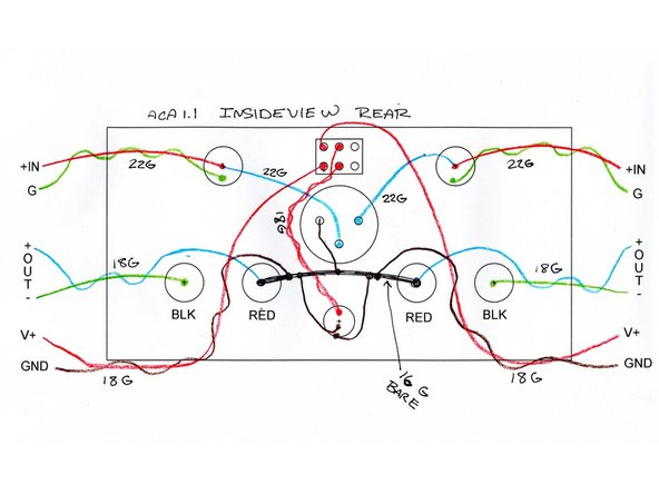
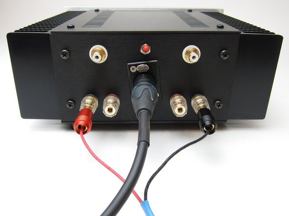
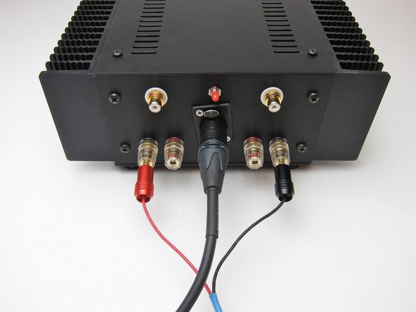
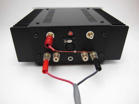
The addition of a standard 3-pin XLR jack and 3 small pieces of wire can make a stereo ACA into a bridge balanced monoblock amplifier. The only catch is the signal must now come from a balanced source or preamp.
-
Output is taken from the black speaker posts
-
See photo for wiring
-
-
-
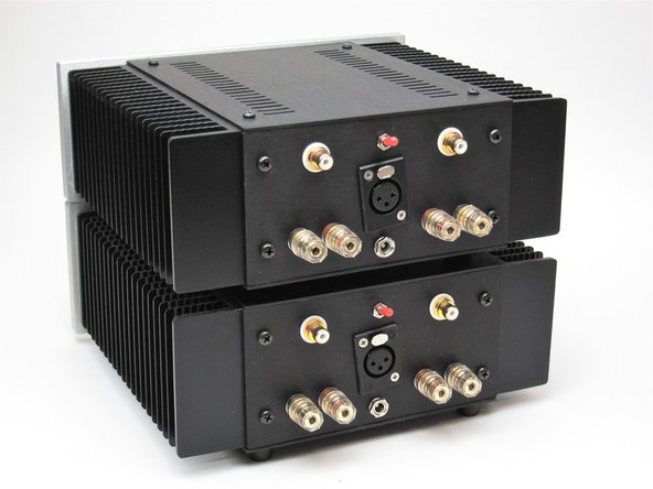
Regardless of how you wire for bridged operation, you'll need two ACAs for stereo now
-
Of note - I used XLR jacks that I had on my shelf from a different product, they have tabs a bit long for the chassis and that's why they are at a slight angle (Use what you have, this is DIY, after all)
-
The hole on the back of the ACA will fit any D series Neutrik jack or more specifically something like the Neutrik NC3FPP.
-
-
-
Nelson Pass: "Being that the channels are inverting in phase, another way is to simply drive one channel and feed its output through an appropriately large value resistor to the input of the other channel, taking the output off both minus outputs of the ACA."
-
Nelson Pass: "Being that the channels are inverting in phase, another way is to simply drive one channel and feed its output through an appropriately large value resistor to the input of the other channel, taking the output off both minus outputs of the ACA."
-
"The result is a bridged amplifier. It will deliver about 15 watts into 8 ohms at clipping, but will not enjoy the distortion cancellation that comes with driving the inputs balanced. The result is still negative phase 2nd harmonic at ordinary levels."
-
-
-
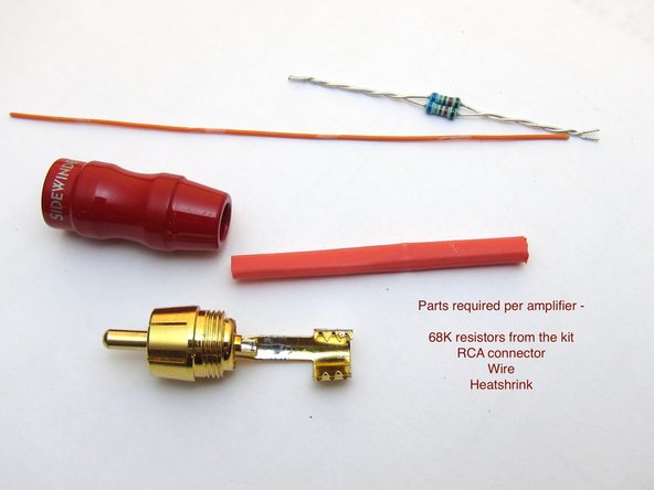
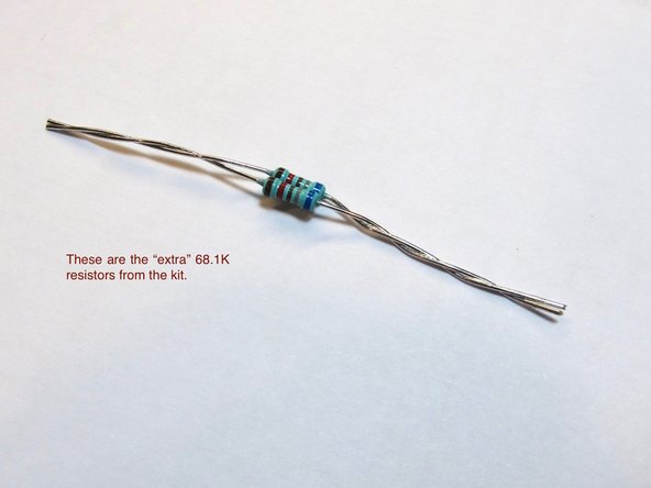
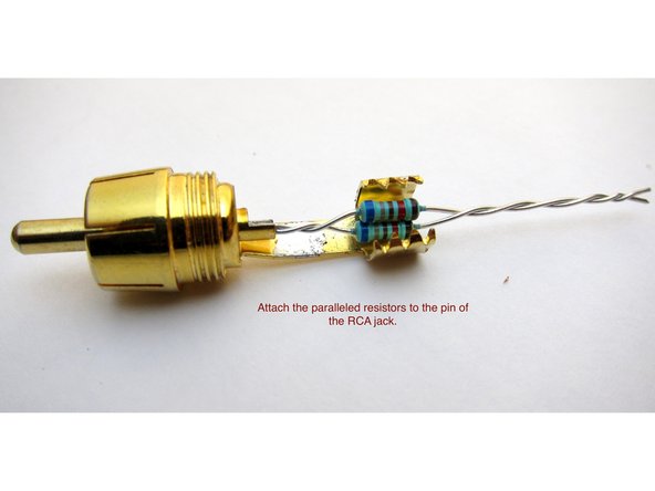
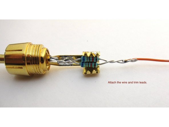
Take the extra 68K resistors from the kit and parallel them to make a 34K resistor. (if you'd like to be super precise, use a 39K for the ideal tuning, but 34K is close enough to not matter much...)
-
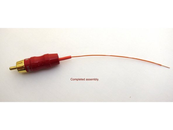
Solder to the pin (+) of an RCA jack and add 5" (120mm) wire.
-
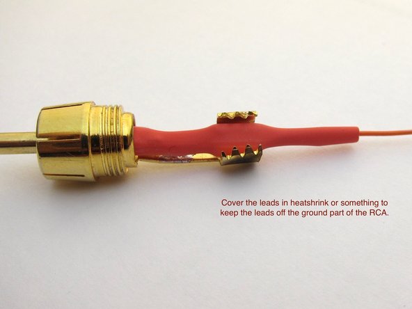
Use some heatshrink or something similar to keep the leads from touching the ground part of the RCA.
-
-
-
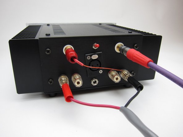
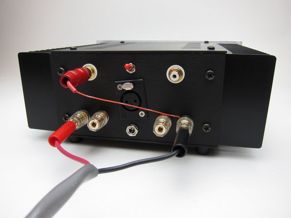
Attach as shown for proper phase.
-
This takes advantage of the inverting character of the amp circuit, and uses the invert through the resistor to feed the other channel of amp to bridge. Clever!!
-
-
-
Discuss your build and ask for help about anything at all in the March 2018 Amp Camp Amp Kit Build Guide Thread
-
Upload photos of your finished product and talk about everything else in the Amp Camp Amp General Discussion Thread
-
We hope you enjoyed the guide! Please discuss your build, ask for help, upload photos and generally join in the diyAudio community discussion threads listed above!
We hope you enjoyed the guide! Please discuss your build, ask for help, upload photos and generally join in the diyAudio community discussion threads listed above!
Cancel: I did not complete this guide.
12 other people completed this guide.


