
Introduction
This is the build guide for the Korg Nutube B1
- NuTube website
- Nelson Pass' original article
- B1K thread on diyAudio
- B1K product page in the diyAudio Store
Please note:
The photos in this guide were made using the pioneer batch chassis which had vents in the covers. The production run of B1K chassis has upgraded covers without vents. This is an intended improvement to the original design that helps control microphonics, based on testing and research from our pioneer batch beta testers.
The photos shown are of the components used in the pioneer batch. The components chosen for the production batch may vary from the photos. We sometimes buy Digikey/Mouser completely out of all their stock of a certain part and "same-or-better" alternates are chosen. Component appearance may vary even between batches from the same manufacturer. Always measure your components before installing them, confirming they match the value printed on the part, and trusting the schematic which is the ultimate source of truth.
If you have any comments or tips on any step please leave a comment. Please note you must first be logged in to diyAudio before you post your comment here. Your comment may be invaluable to other builders!
-
-
Download a high resolution PDF version of the B1K Schematic
-
Download a high resolution PDF version of the B1K Wiring Diagrams
-
Print these PDFs and keep them next to you while you build
-
-
-
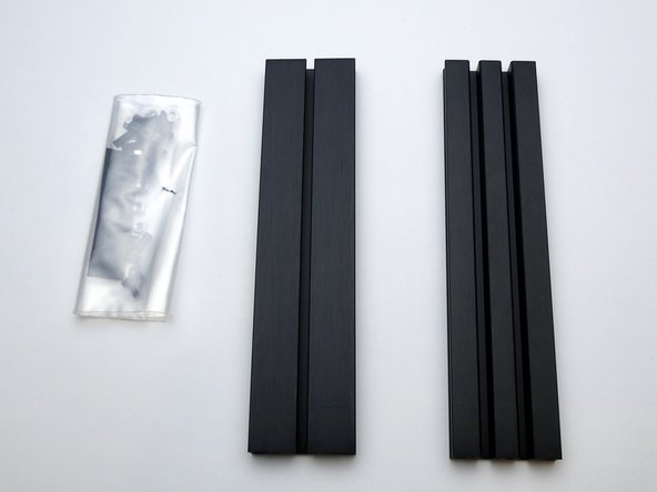
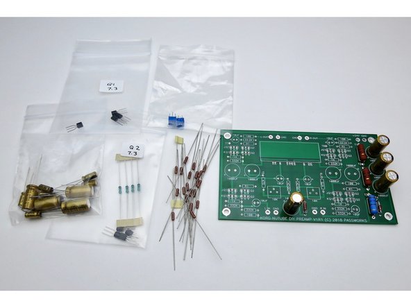
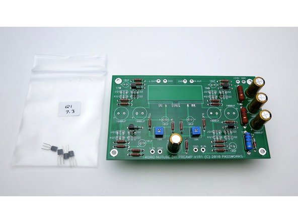
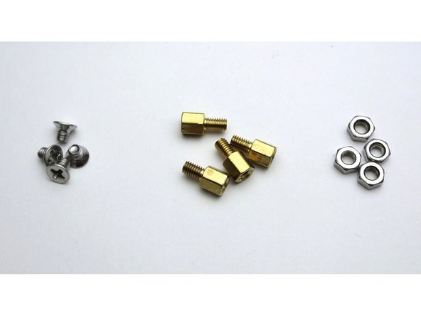
Gather these parts (Well, you don't actually need the knob right now... )
-
Note that the toggle switches are identical
-
-
-
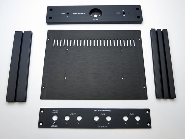
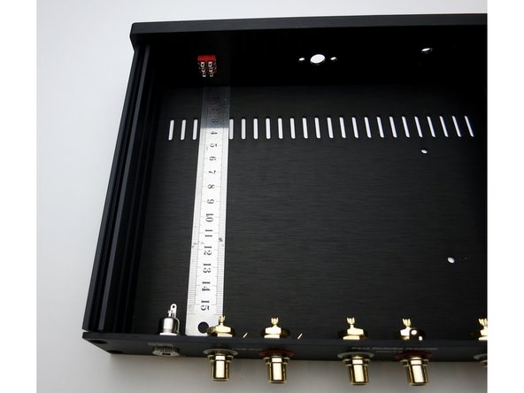
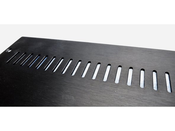
Photo 3 - The bottom panel has the 4 holes drilled for the PCB standoffs
-
The photos in this guide were made using the pioneer batch chassis which had vents in the covers. The production run of B1K chassis has upgraded covers without vents. This is an intended improvement to the original design that helps control microphonics, based on testing and research from our pioneer batch beta testers.
-
-
-
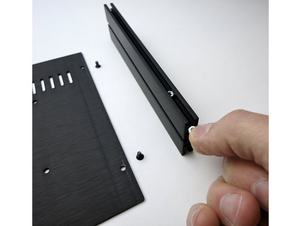
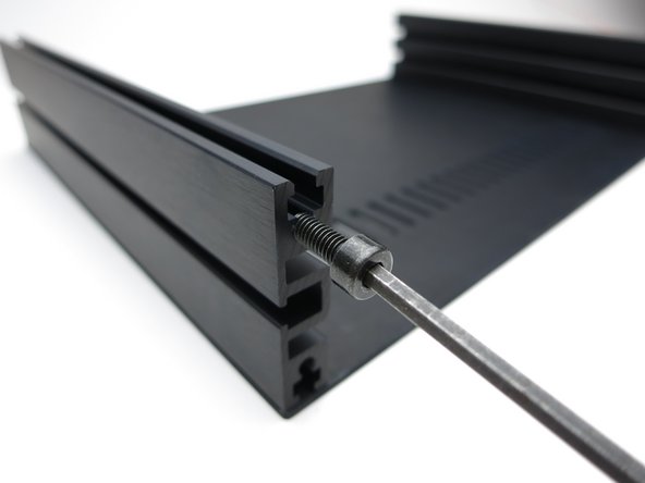
Insert the nuts into the channel
-
-
-
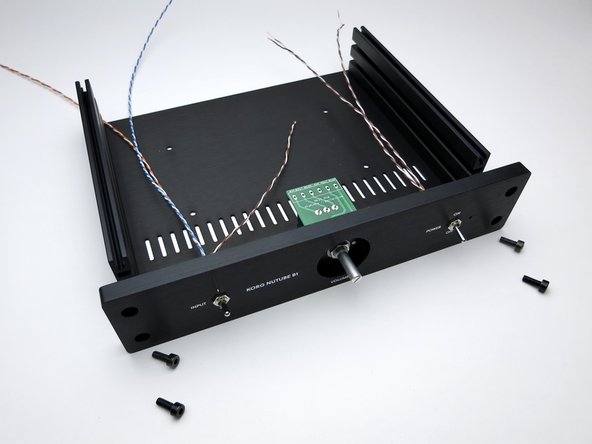
Slide the nuts under the holes then attach the screws
-
-
-
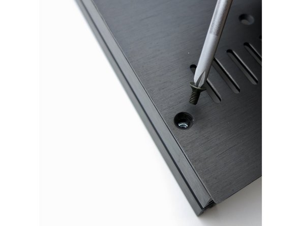
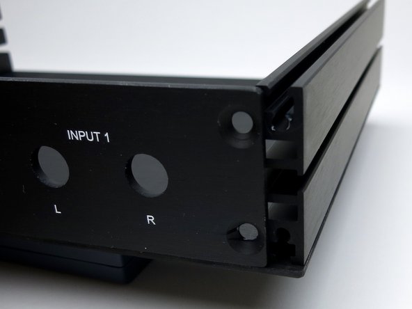
Make sure the holes are aligned with the threaded part of the aluminum extrusion, not the square channel where the nuts go.
-
-
-
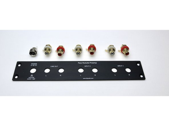
Back panel
-
-
-
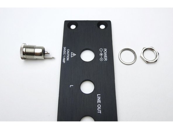
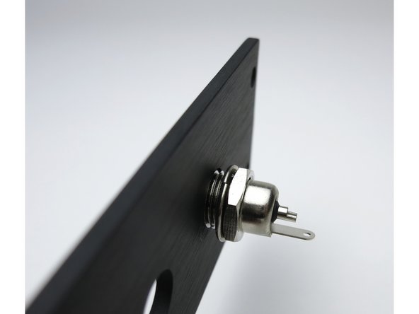
Barrel jack assembly
-
-
-
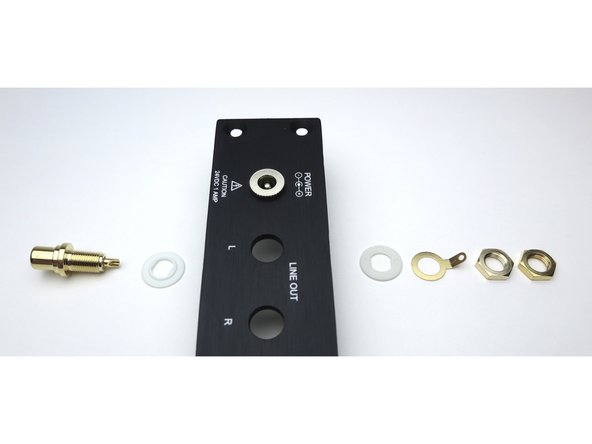
RCA assembly
-
Photo 2 - RCA jack positioning
-
-
-
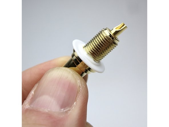
Place the shoulder washer here as shown
-
-
-
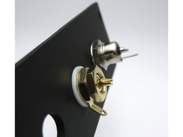
Align tabs as shown
-
-
-
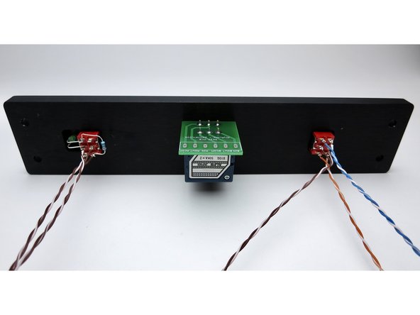
Barrel jacks attached
-
-
-
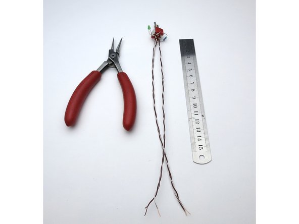
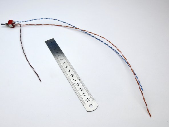
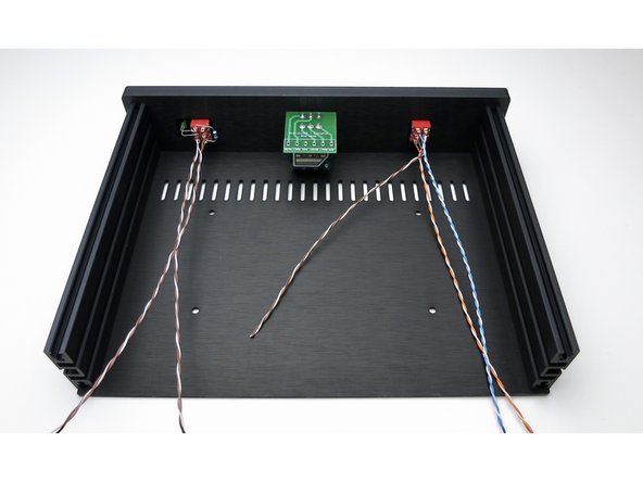
Make the leads long now and trim them to size later.
Here is a good spot to point out that you will also need to use a small section the brown/white pair of wire for the connection from the input switch to the potentiometer a bit later on.
Cut off about 4” to 5” (100-120mm) of wire now for this later use. The remaining longer brown/white section of wire can then be in half (about 8” to 9” each or 200-220mm) to be used for the power connections. So you should start off with two 8 to 9” (200-220mm) lengths and one 4 to 5” (100-120mm) piece.
I missed this part and simply cut the whole length in half at first, then didn’t have enough left over to make the switch-to-pot connection later on and ended up having to use different wire. Not a big deal, but it is nice to keep the color codes the same as in the guide to aid in troubleshooting later on if the need arises.
-
-
-
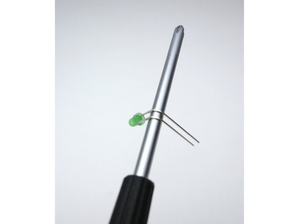
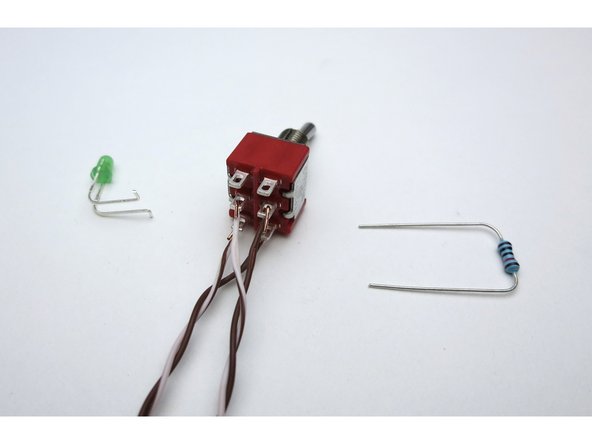
Begin with the LED
-
-
-
Bend the LED 90deg around the curve of a screwdriver. Long leg on top.
-
-
-
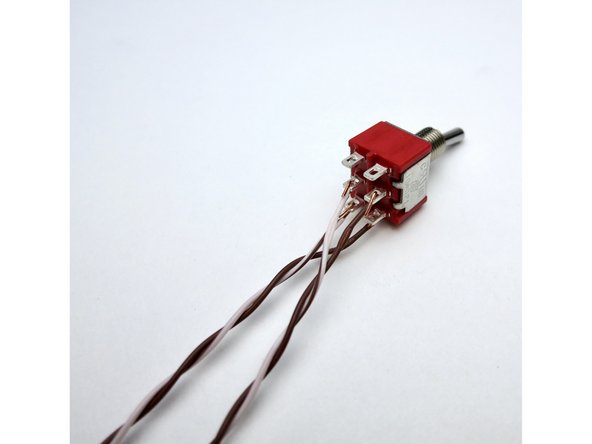
Wires attached as shown
-
-
-
LED and resistor as shown. Making a couple of bends where the LED attaches to the switch will greatly aid assembly.
-
-
-
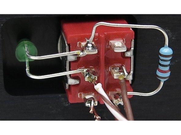
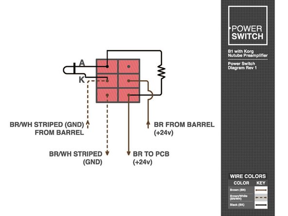
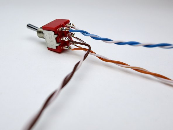
Photo 1 - Assembled switch
-
Photo 2 - LED/Resistor wiring
-
Photo 3 - Wiring diagram
-
-
-
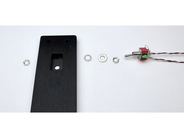
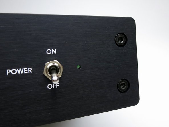
Assemble switch to front panel - nut/front panel/star washer/flat washer/nut.
-
-
-
It's easier to make the wires long now and trim to size when soldering. Please note that you don't have to follow my color scheme, but if you do checking things will be much easier... For that matter you can substitute other wire if you like. It's DIY, after all.
-
-
-
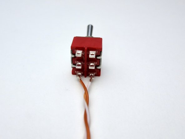
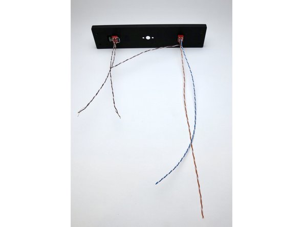
Photo 1 - Solid colors on the left, white traces on the right. Begin with orange on the bottom. Note that there is no "top" or "bottom" to the switch until you attach things to it.
-
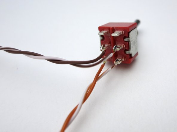
Photo 2 - Brown in the middle, this will go to the potentiometer.
-
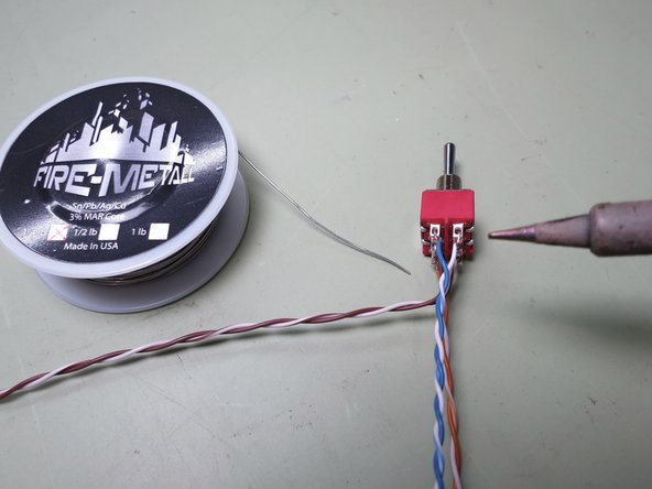
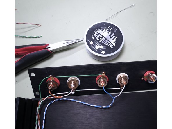
Photo 3 - Blue on top. (Shameless plug: the Fire-Metall solder is absolutely the nicest I have ever used. )
-
Later, in step 52, the orange and blue pairs will be connected to inputs 1 and 2 on the rear panel
-
-
-
Complete. Mount the selector switch into the front panel using the same technique you used for the power switch.
-
-
-
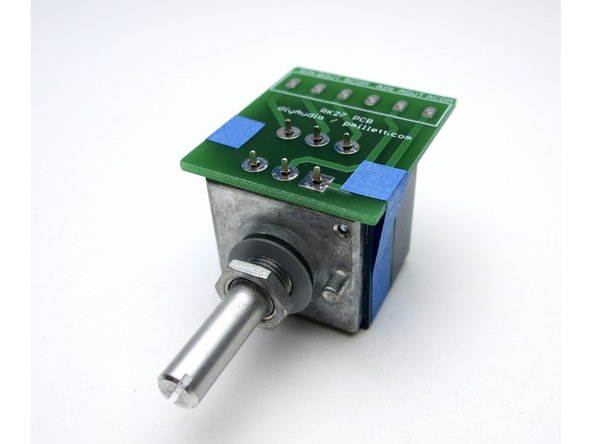
Photo 3 - A little tape helps keep everything in place when soldering the PCB.
-
-
-
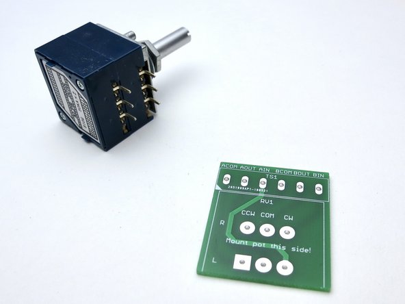
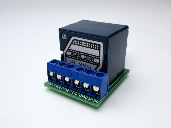
Photo 2 - The screw terminals mount as shown if you want to use them.
-
-
-
Front panel wiring.
-
-
-
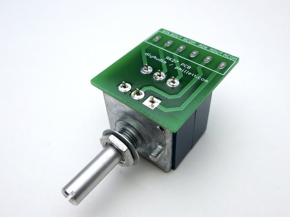
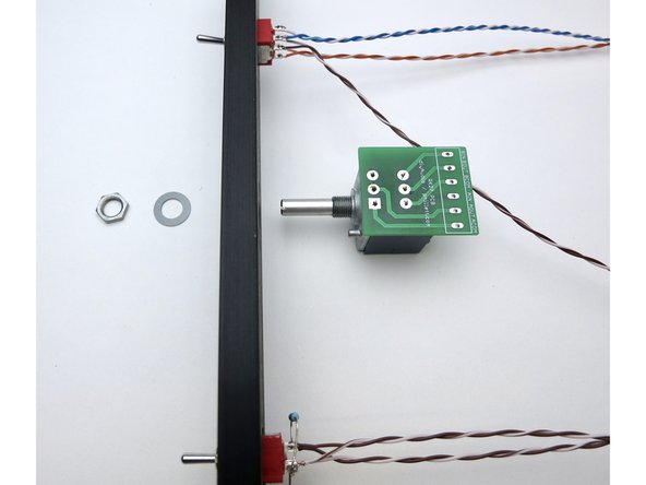
Photo 1 - Install potentiometer to the front panel
-
-
-
Photo 3 - The screws go the threaded section, not the channel where the nuts are.
-
-
-
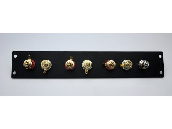
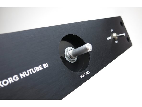
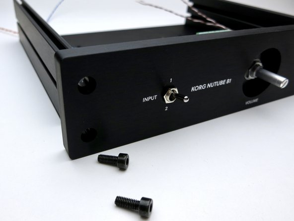
Photo 1 - Front panel should look like this now.
-
Photo 2 - Hopefully you can get your chrome nut on the switches better aligned than this.
-
-
-
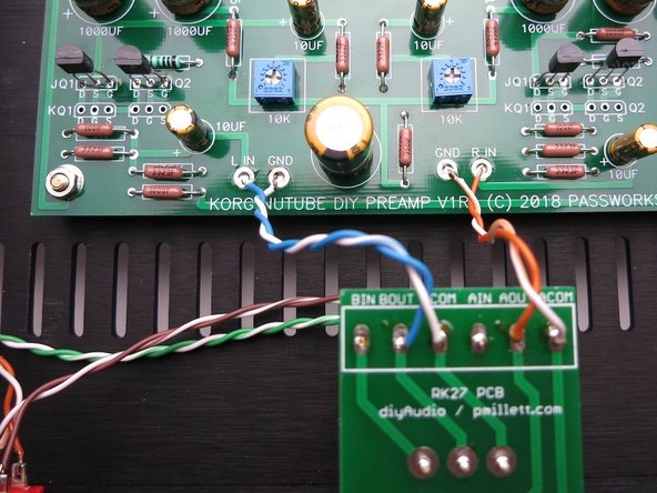
Photo 2 - The middle of the switch needs to be connected to the IN pads of the pot board. In our wiring scheme so far, solid colors are right and white/trace color are left
-
Photo 3 - Grounds are connected to the COM pads and go directly to the input RCAs, not connecting to the switch. Solid green is right, white/green left.
-
Do not solder yet!
-
-
-
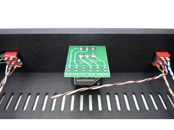
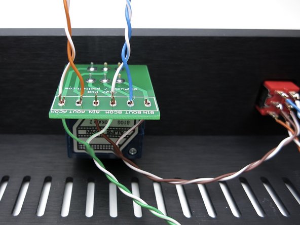
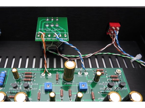
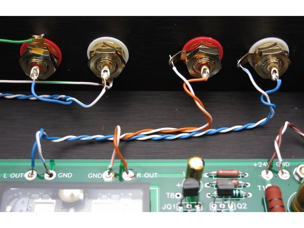
Top connections, left to right in the photo:
-
ACOM: Orange/White, AOUT: Orange
-
BCOM: Blue/White, BOUT: Blue
-
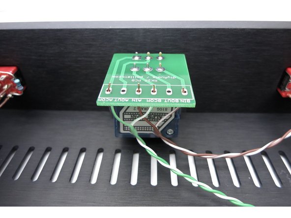
Bottom connections, left to right in the photo:
-
ACOM: Green, AIN: Brown
-
BCOM: Green/White, BIN: Brown/White
-
Later, in step 52, the the pairs of orange and blue wires coming out of the top of the RK27 board will be connected to the left and right inputs on the main circuit board
-
-
-
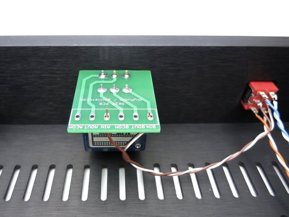
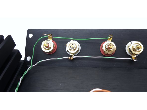
Remember green is input grounds, and go directly to the potentiometer.
-
-
-
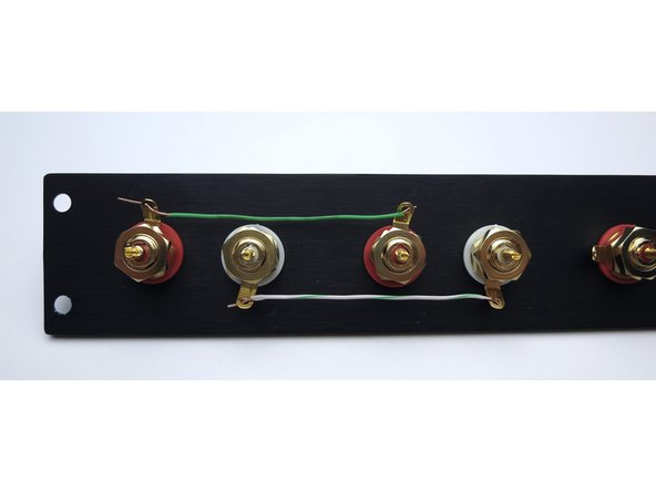
Photo 1 - Ground tabs tied together as shown. Solid green to right ground tabs, white/grn to left tabs.
-
Photo 3 - Orange is input one. Solid orange to right, white/orange to left. Blue is input 2. Solid blue to right, white/blue to left.
-
-
-
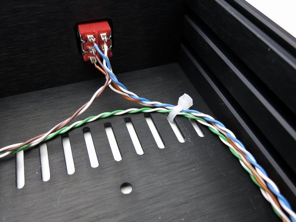
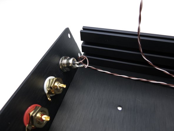
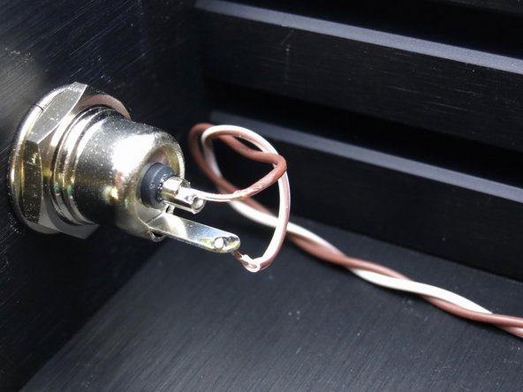
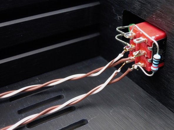
Photo 1 - Wires to middle of front panel power switch. Brown is barrel center, white/brn is tab (photo 3).
-
-
-
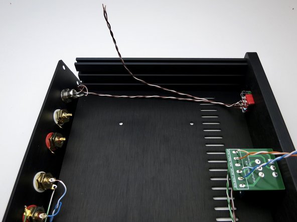
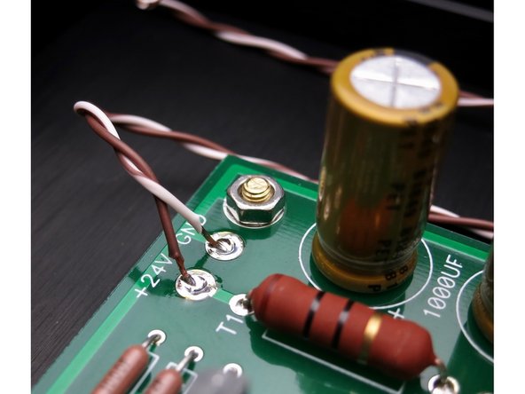
Wires from the bottom of this switch (photo 1) connect to the PCB (photo 2). Brown is +24V, brown/wht is GND
-
-
-
The photos of the Barrel-Power Switch-PCB wiring are for clarification. PCB Stuffing, starting with the PSU is next.
-
-
-
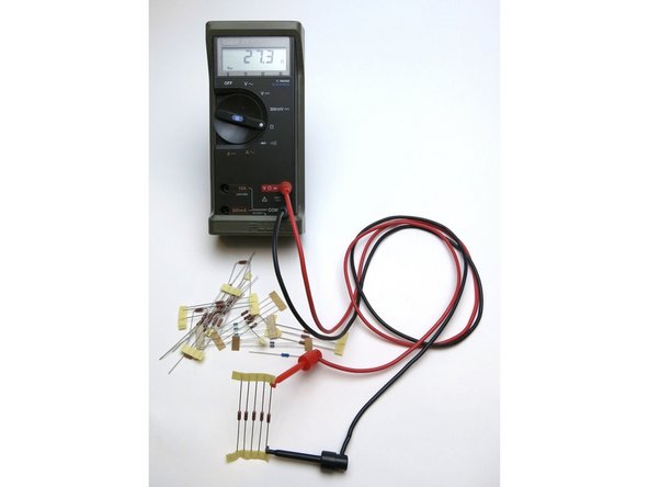
Measure all resistors before inserting into the board.
-
-
-
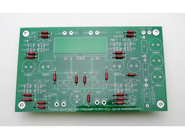
PSU section is stuffed and tested first. Please do not stuff entire PCB at once.
-
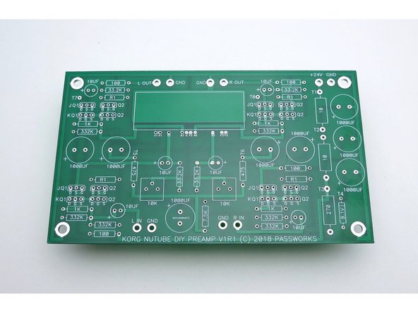
Bare PCB V1R1 is the most current as of this writing (Spring 2020)
-
-
-
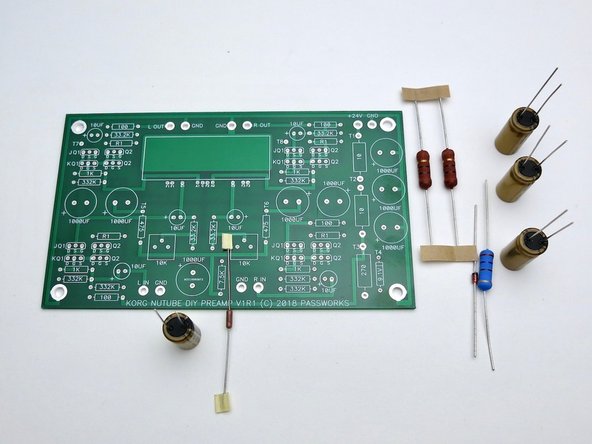
We need to assemble and test the PSU first. Get these components, they are in the top part of the schematic. This section is common to both L and R channels.
-
As always, print the schematic and have in front of you as you build.
-
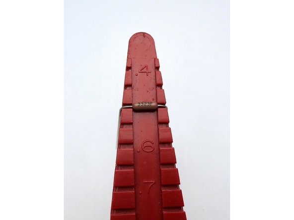
Photo 2 - If you have a lead bend tool, the small resistors and diode are on 0.5" spacing. The large resistors are 0.75", but you can just bend those leads straight down and it will be close enough.
check the orientation of the diode. the black strip should match the line on the PCB
dlucksinger - Resolved on Release Reply
-
-
-
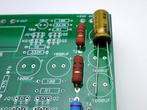
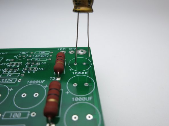
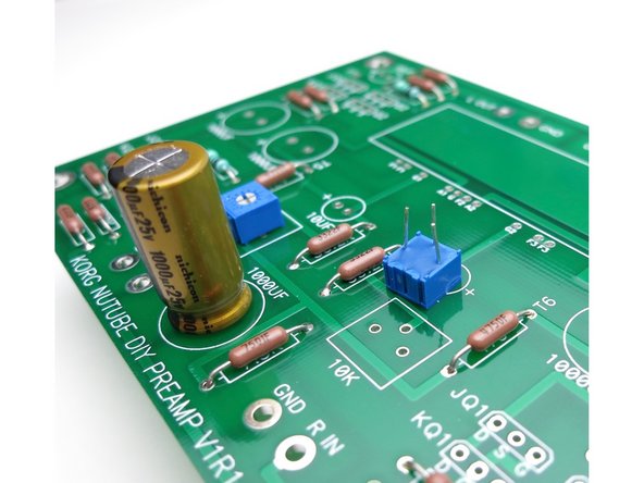
Capacitors have polarity. The negative is marked on the can, and the positive is the long leg. Also note the PCB has the + marked.
-
Photo 2 = Long leg into +
-
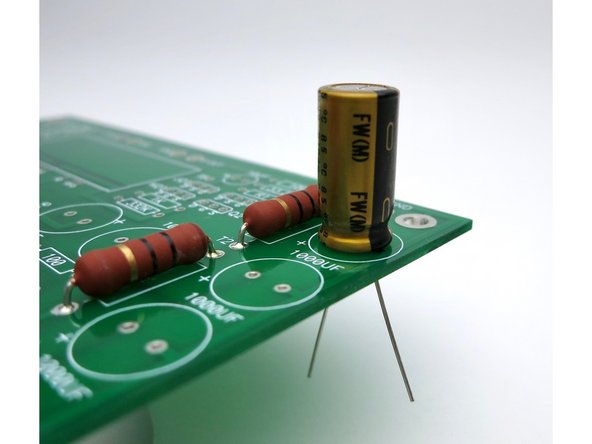
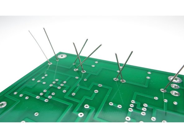
Photo 3 - Bend the leads out a little to keep the components in the PCB before soldering.
-
-
-
Photo 2 - When you get these components stuffed stop and test the PSU.
-
Get the wall wart, the wired chassis, a piece of paper or something non-conductive to insulate the board from the metal, and the PCB Wires from middle of power switch. Brown is barrel center, white/brn is tab.
-
-
-
Photo 1 - Wires from middle of power switch. Brown is barrel center, white/brn is tab.
-
Photo 2 - Wires from bottom of switch to the PCB. Brown is +24V, brown/wht is GND
-
Photo 3 - Power switch wires connected tp PCB
-
-
-
Attach PSU switch as shown. Ignore the fully stuffed PCB in the photo, it should only have PSU components on it right now!!
-
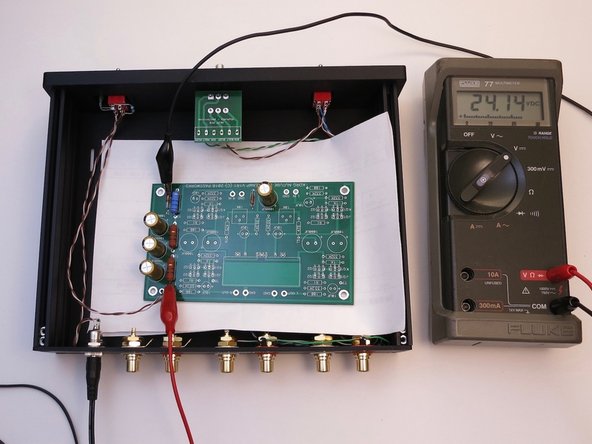
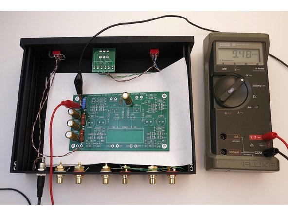
Connect the power switch wires to the PCB (Step 40 - Photo 3) and power it on. Connect meter to places shown and you should have about 24V.
-
Rest the PCB on a piece of paper to keep it from touching the metal chassis.
-
-
-
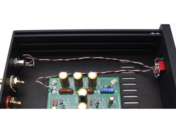
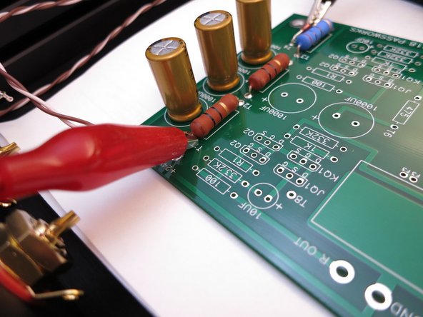
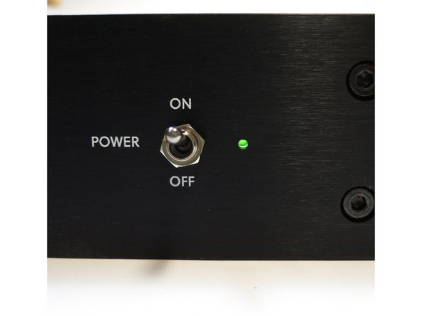
Photo 1 - Also check the chassis LED
-
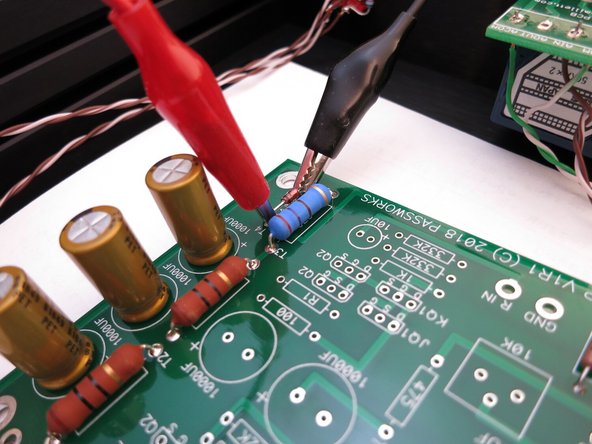
Photo 2 - Move the multimeter red to the top (black band) leg of the diode and check the voltage of about 9.5V
-
Photo 3 - If you have these readings, turn it all off, unsolder the Main PCB from the wires and continue.
-
-
-
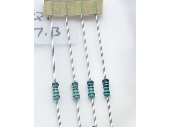
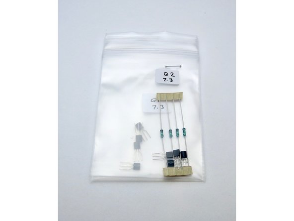
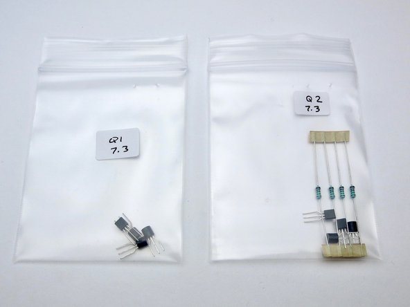
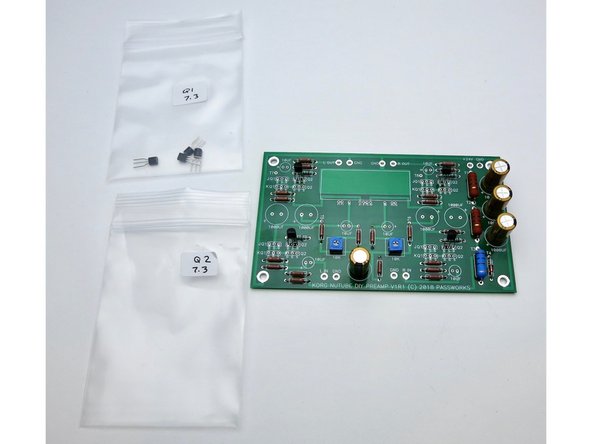
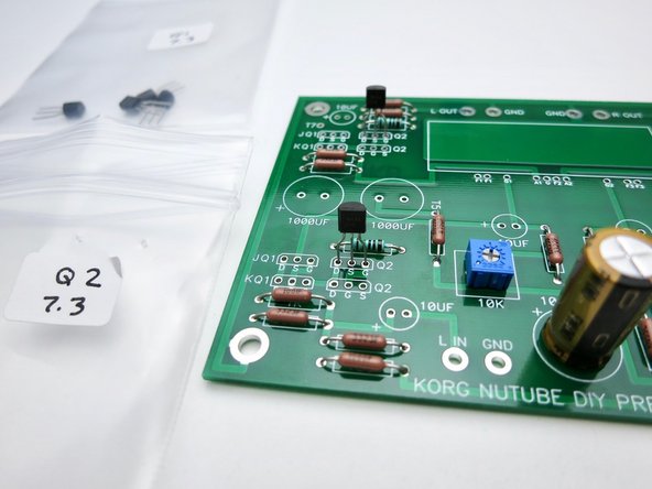
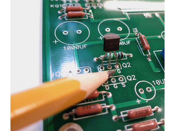
The PCB kit comes with two bags with 4 transistors in each (8 total), and 4 resistors, don't mix them up, and don't lose the resistors, as they are selected for those specific transistors, in your kit.
-
-
-
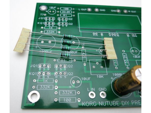
The resistors go into the spot marked "R1" on the PCB, there are (4) places. Photo 1 - These locations have no value printed on them nor does the schematic have a value. They are selected to mate with the included transistors.
-
Photo 2 - Gather the rest of the PCB parts
-
Photo 3 - As mentioned earlier, the resistors are all on 0.5" lead spacing
-
-
-
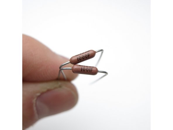
Photo 1 - The Dale resistors have their value marked in digits on the side This is 3-digit+multiplier The top resistor is 100 ohms -- 100+0, or "one hundred ohms and zero zeroes" The bottom is 1K -- 100+1, "one hundred and one zero"
-
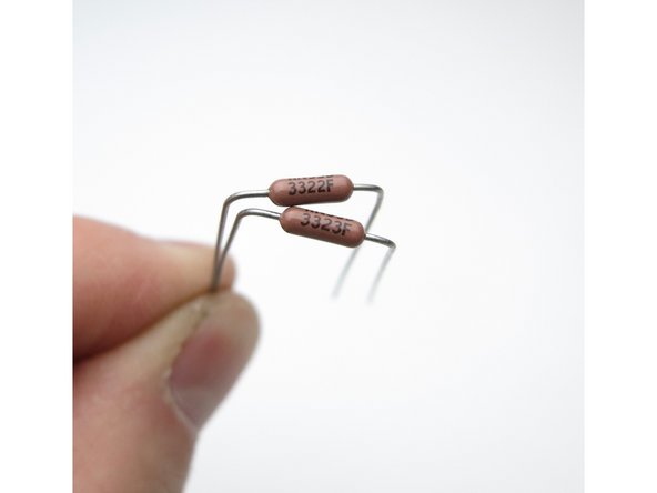
Photo 2 - Top 33.2K "332 + two zeroes" Bottom 332K "332 + three zeroes"
-
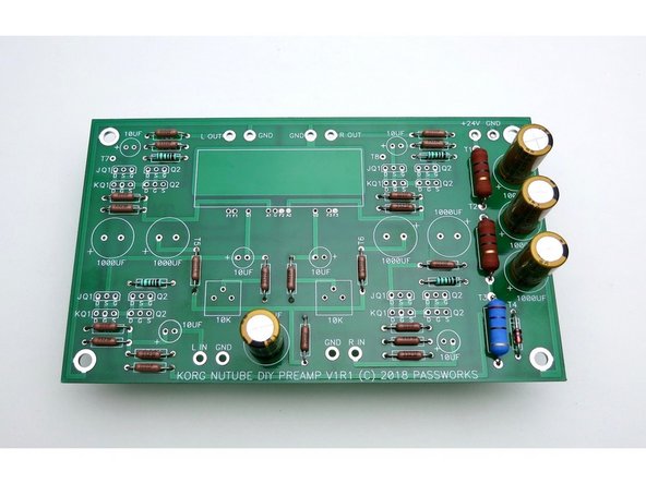
Photo 3 - Stuff all the resistors. The value is printed on the PCB except for the "R1" positions. Neatness counts. Bend all the leads so the value is on top and readable. Insert them into the PCB so the values read left to right or bottom to top. (On the R1s, put the thicker brown band to the right)
-
-
-
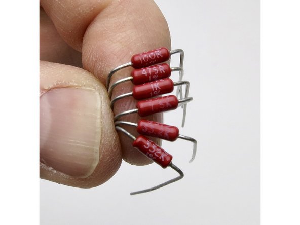
The Autumn 2020 kits include PRP 9327 series resistors. These audio grade resistors are red and have the value printed directly on the body of the resistor with no code.
-
Top to bottom, 100R, 457R, 1K, 7.5K, 33.2K, 332K.
-
Photo 2 - reference of the location of the PRP (red) or Dale (tan) resistor locations.
-
Yes, the printing on the PRP can be a little tricky to see in photos. It's better in real life. The red also looks fantastic on the green PCB :)
-
-
-
Trimmer potentiometers
-
Photo 2 - There are two rows in each position for Jfets, one marked "JQ1 Q2" the other marked "KQ1 Q2" …These boards will allow the use of different JFETs. If you purchased the full kit, ONLY stuff the locations marked with J. The rows with the J are for the J113 parts (Fairchild, included in the kits)
-
The rows with K are for K170 parts (Toshiba, not included) Only use one or the other! You don't need to use both rows. Open one bag at a time so you don't mix them up.
-
Photo 3 - Kit parts use the "J" row
-
-
-
Photo 1 - You can solder one leg from the top to keep them in place when you solder the bottom.
-
Photo 2 - Stuff the other bag
-
Photo 3 - Jfets complete
-
-
-
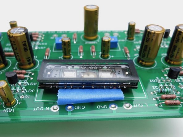
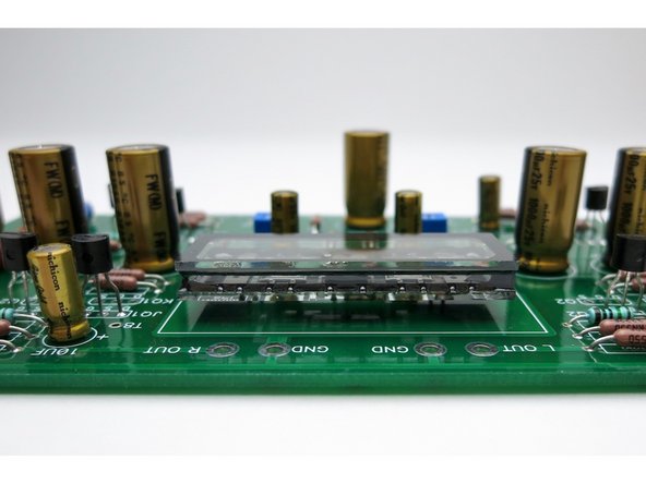
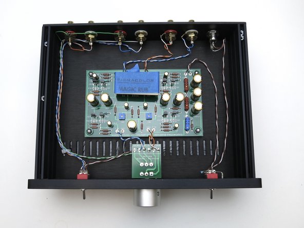
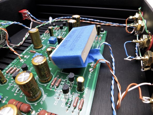
Photo 1 - NuTube is next. Make a loop of tape under the NuTube to make some room above the PCB, you don't want it to touch. Solder the pins
-
Photo 2 - Let it float above the board
-
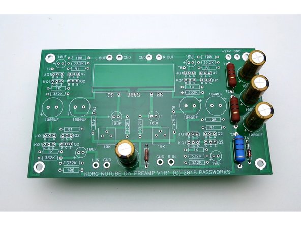
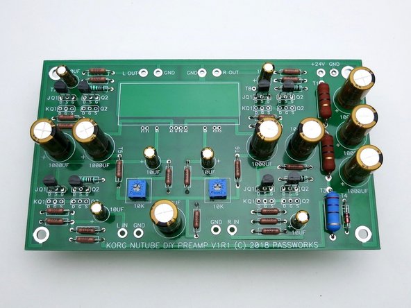
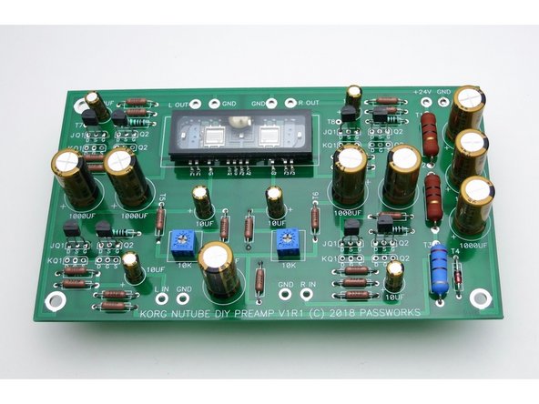
Photo 3 - Fully stuffed PCB
-
-
-
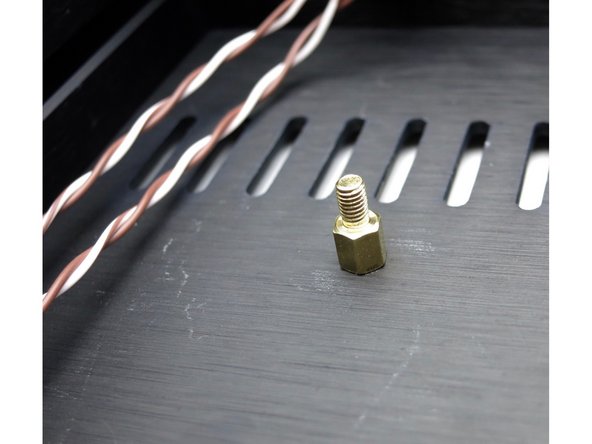
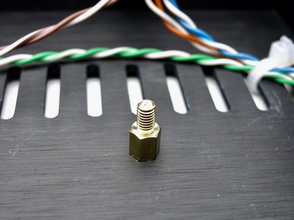
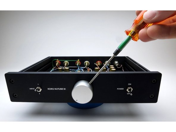
The standoffs attach to the inside of the bottom panel.
-
-
-
Attach wires from potentiometer to Korg PCB Blue and white/blue for Left. Orange and white/orange for Right.
-
-
-
Photo 1 - Attach output RCAs as shown. We will use the same colors as the short leads from the pot board to the main PCB.
-
Photo 2 - Attach knob
-
-
-
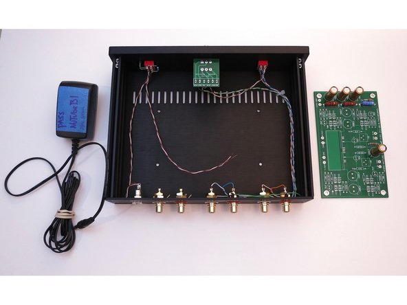
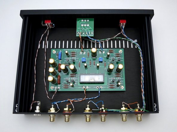
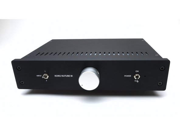
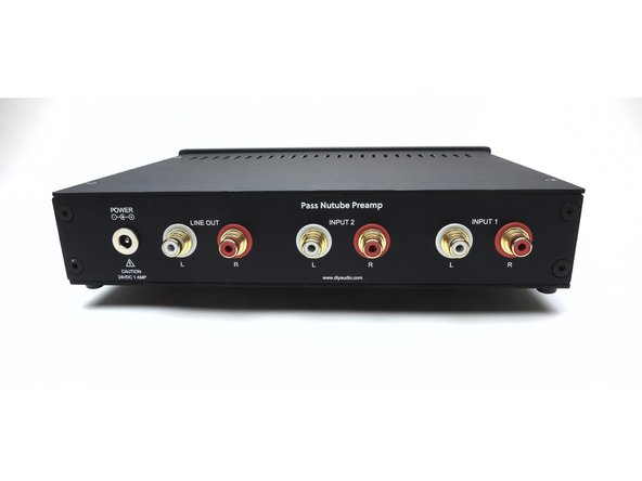
Front & rear views of completed kit.
-
-
-
The Nutube can be microphonic. Everybody will hear it when they flip a switch, but some of the Nutube themselves are worse than others, it seems to be the vagaries of production.
-
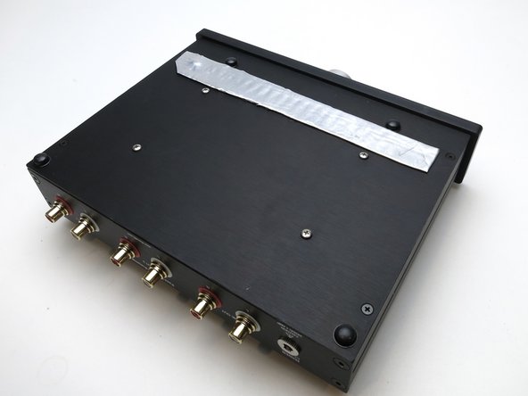
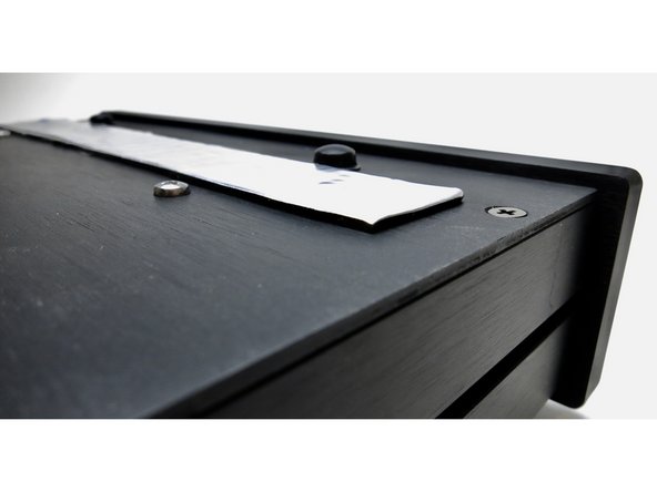
I tried a number of different solutions and the best results were to take a white latex pencil eraser to the to top of the glass, and then seal up the vent holes in the chassis. Newer chassis will not have vent holes.
-
This is a self-adhesive rubberized material similar to Dynamat.
-
-
-
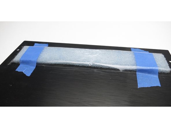
If you have the production run of the B1K you can skip this step. This step is only relevant to the pioneer batch of chassis which has vents in the covers.
-
Photo 2 - This is just some closed-cell shipping foam taped to the inside of the vents. Both it and the sticky foil-backed material worked well. Blocking it seems to be more important than absorbing or damping.
-
If anybody has suggestions or examples of what works, please share them!
-
-
-
Pete Millett's NuTube anti-vibration mount makes a very good improvement. Very highly recommended.
-
-


We hope you enjoyed the guide! Please discuss your build, ask for help, upload photos and generally join in the diyAudio community discussion threads.
We hope you enjoyed the guide! Please discuss your build, ask for help, upload photos and generally join in the diyAudio community discussion threads.
Cancel: I did not complete this guide.
22 other people completed this guide.