
Introduction
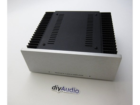
This is the build guide for the Amp Camp Amp v1.6.
The differences between the 1.5 and 1.6 are fairly minor - the circuit is identical to the previous version, all the parts other than some chassis mounted components are the same. The schematic is the same, and part numbers are the same. The biggest changes are a different layout of the PCB, inclusion a front mount power switch, and the rear switch is now used for RCA input stereo/mono.
Please note that the wire colors have changed in batch 3. While some colors are unchanged, there are now more unique color pairs, and we have updated the wiring diagrams with the new colors, however the photos and videos in the guide have not yet been updated. Please print out the correct wiring diagram to match your batch (steps 33 and 34), and refer to it while you build.
If you have any comments or tips on any step please leave a comment. Please note you must first be logged in to diyAudio before you post your comment here. Your comment may be invaluable to other builders!
-
-
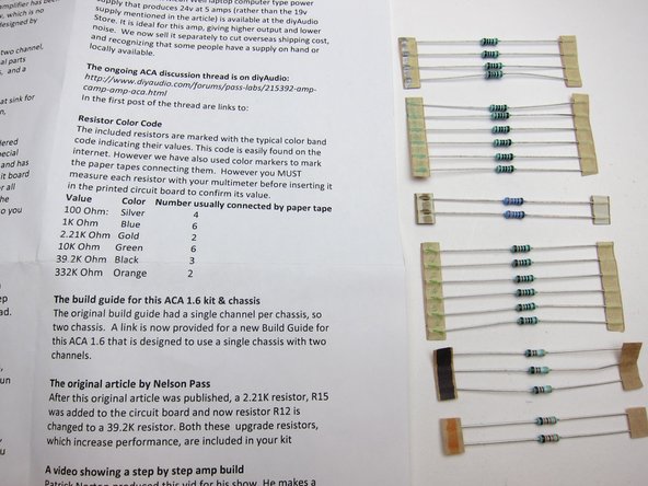
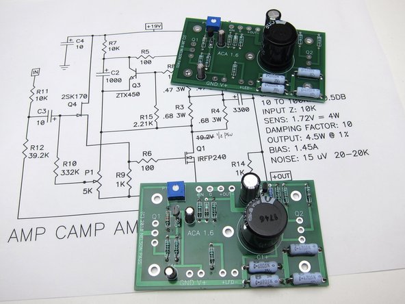
Print this out on paper and have it in front of you during the whole process.
-
-
-
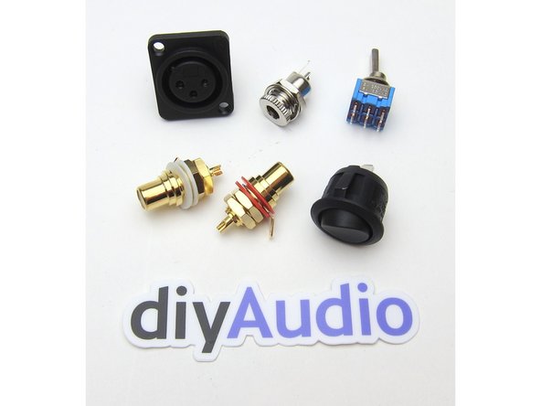
The various components are all found in individual bags as shown.
-
-
-
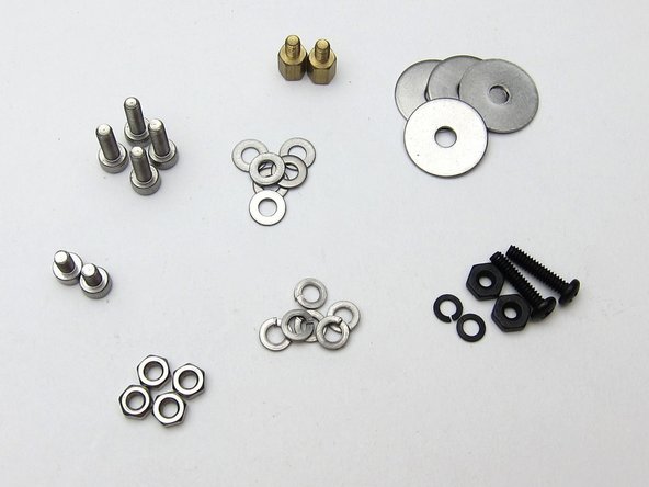
In the various bags of the kits you will find hardware,
-
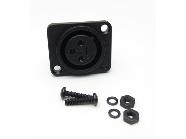
The XLR jack,
-
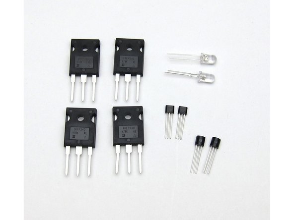
The transistors and LEDs.
-
The big transistors are the Mosfets (Q1 Q2), The smaller of the two other transistors is the ZTX450 (Q3), and the slightly bigger one is the input Jfet (Q4)
-
-
-
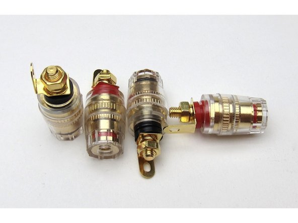
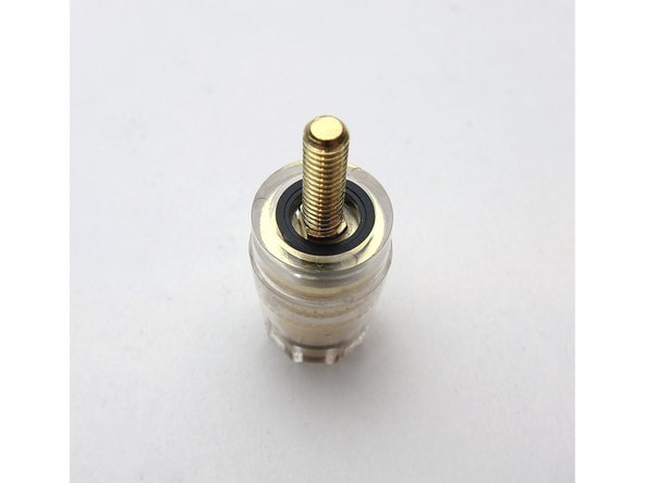
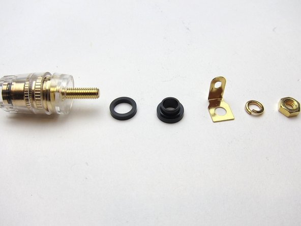
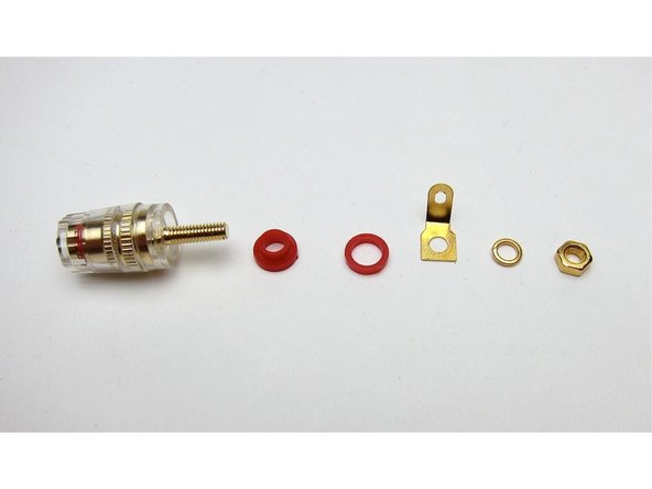
Speaker posts.
-
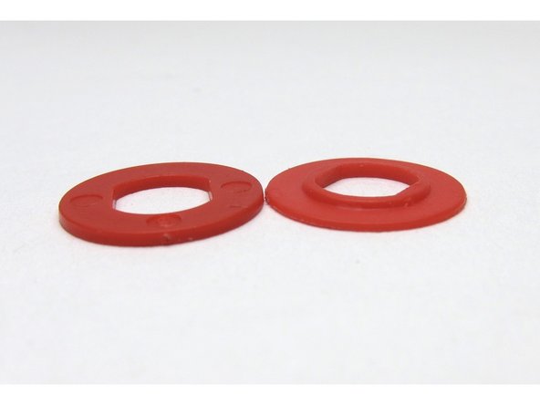
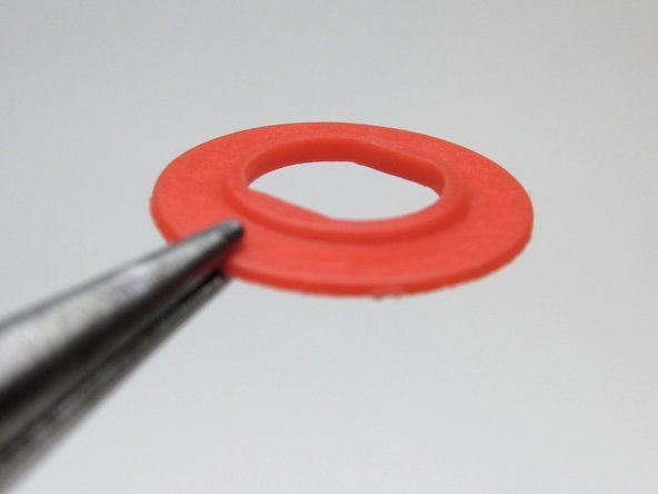
Try the washers in the posts as shown, some posts will fit the small washer flush on this side, some will fit the shoulder washer on this side.
-
It doesn't matter if the shoulder comes first or the other plastic washer, as long as things sit squarely and the shoulder washer is inserted through the chassis so the threaded portion doesn't touch the back panel itself.
-
-
-
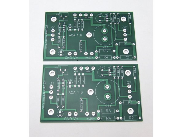
Now we will stuff and solder the components onto the PCB.
-
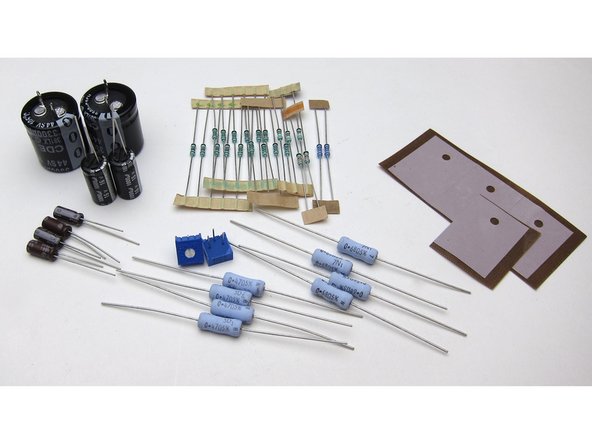
Get the resistors and capacitors, and place the keratherm insulators aside for the moment.
-
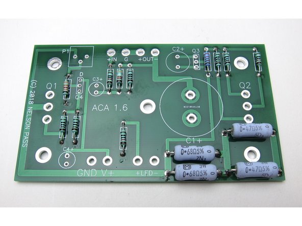
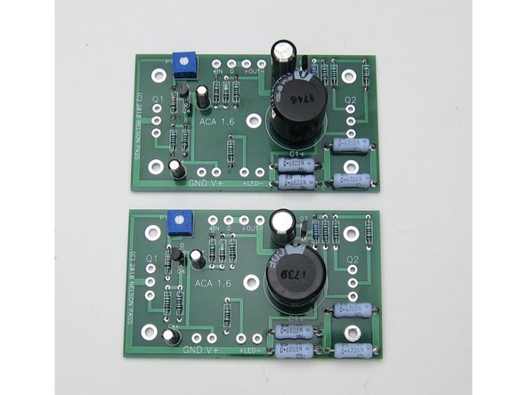
Image 3 shows the two properly stuffed PCB, assisted by the fact that the schematic was printed out and referred to during the whole process. :) :) :)
-
-
-
Measure EVERY RESISTOR before placing in the board :)
-
Panasonic power resistors: It's difficult to measure these because the resistance of your multimeter leads (normally 0.2-0.4Ω) will be added. You can measure your leads and subtract the value, just trust the values which are printed on them, or build a low resistance value test rig.
-
Have the schematic printed in front of you at all times. The schematic marked 1.1 is correct for the 1.6
-
The resistor tape is marked in a way shown on the documentation in the box. Measure everything regardless.
-
-
-
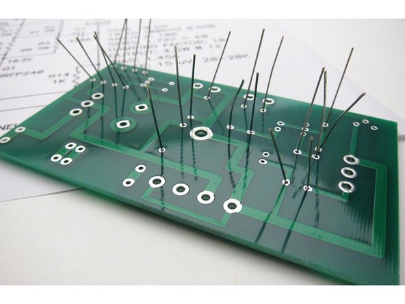
Generally it's easiest to start stuffing the PCBs with the smallest components first - in this case the resistors.
-
Note the 1% resistors all have a brown band at one end - to help assist troubleshooting in the future if needed, place the brown at the bottom of all resistors.
-
Slightly bend out leads before soldering
-
-
-
Please watch this excellent YouTube video on How To Solder from Mr Carlson's Lab for a good how-to-solder video. You are probably looking to have your soldering iron set to 350-400'C.
-
We highly recommended a leaded eutectic solder for many reasons. Please see our guides page on which solder to purchase.
-
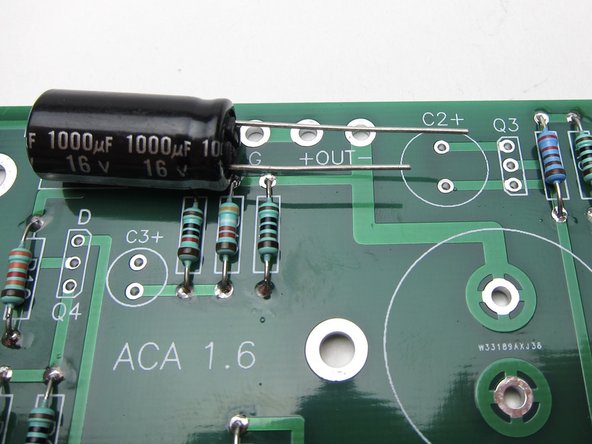
The first photo shows the big and little resistors in their places. Note the large resistors have the value printed right on them - try to bend the leads so the values show and align as shown.
-
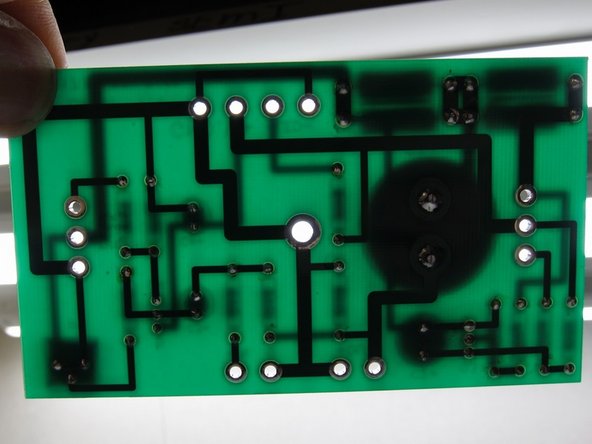
The second photo shows that if you hold the PCB up to the light, you can see if you missed any solder holes
-
Arrange resistors with values upwards, so you can read them after they have been soldered in place.
-
Power resistors: It's difficult to measure these because the resistance of your multimeter leads (normally 0.2-0.4Ω) will be added. You can measure your leads and subtract the value, or read the values which are printed on them.
-
Power resistors: They do get hot and over a long period of time might discolor the PCB. Put a spacer underneath them (like a piece of cardboard) to create an air gap of a few mm, and remove it after soldering them in place.
-
-
-
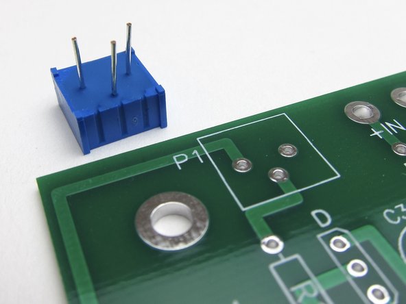
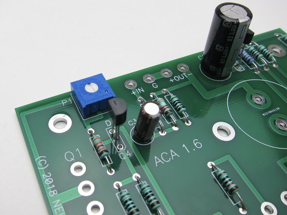
The potentiometers have three leads in a triangular formation, they are impossible to insert backwards.
-
-
-
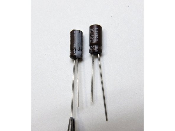
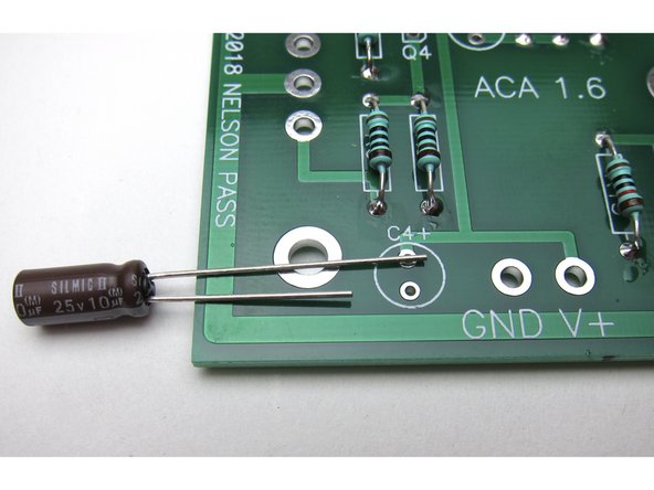
Capacitors have polarity - the long leg is Positive +, and the mark on the can shows negative -
-
Second and third image show: Long leg in the positive marked hole
-
-
-
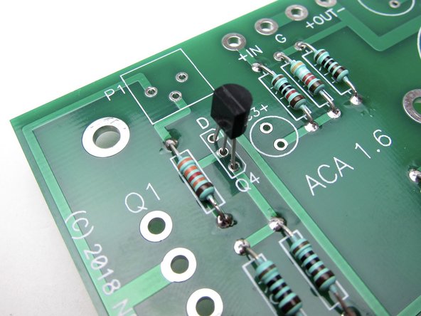
Align the flat of the small transistors with the silkscreen as shown.
-
Q4 is the input Toshiba or LS Jfet, marked K370 or K170 on the flat of the package.
-
Place Q4
-
-
-
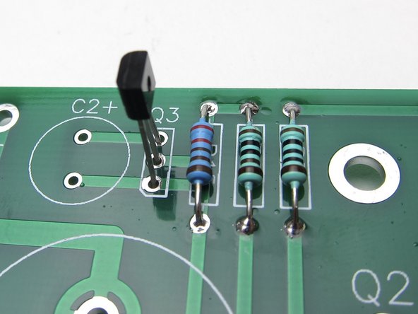
Place Q3. ZTX450 Like the other small transistor the flat of the transistor package matches the flat of the silkscreen.
-
-
-
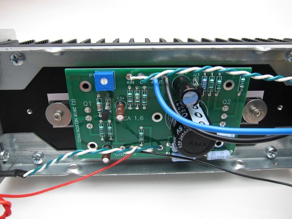
Complete stuffed PCB shown here. Note transistor and capacitor alignment.
-
-
-
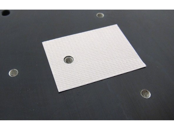
Keratherm is a great modern replacement for the (sometimes toxic and always messy) thermal conducting goop w/insulators required to insulate transistors to heatsinks.
-
The Keratherm is used to electrically insulate the transistor's metal back (Drain) from the metal chassis. And thin enough to allow heat to be transferred from the transistor to the chassis effectively.
-
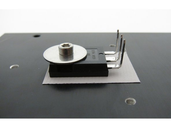
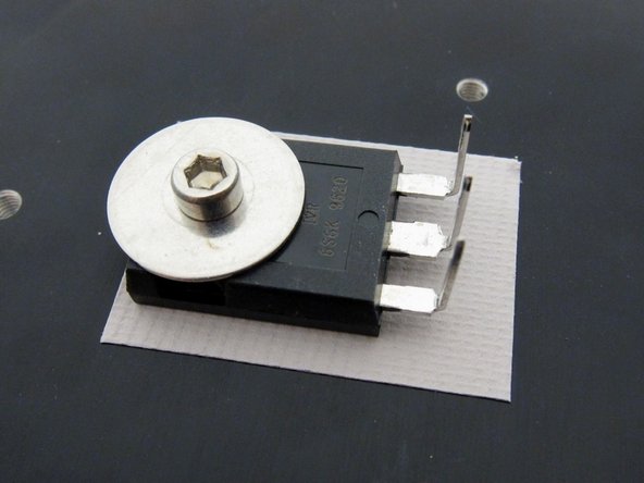
Big transistors mount as shown here, and gently bend the legs up right at the point that they narrow.
-
There should be a lock washer (split washer, spring washer) between the fender washer and the screws.
-
Use a 2.5mm hex wrench to gently tighten the bolts
-
-
-
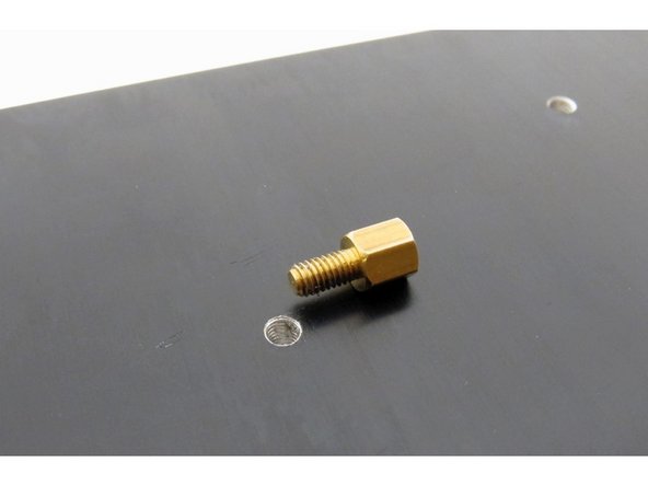
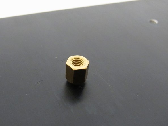
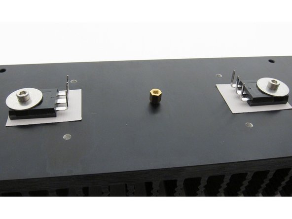
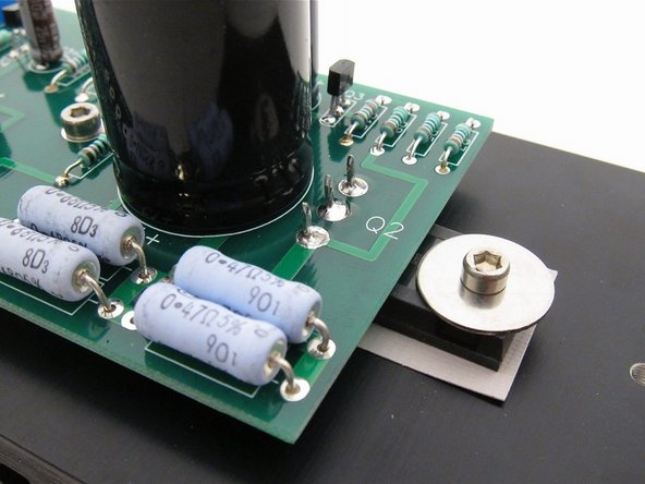
Before mounting circuit board, attach a standoff to the heatsink. Do not over-tighten!
-
It does not have to insert all the way flush into the heatsink.
-
-
-
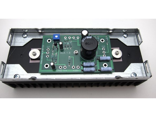
One screw and washer to hold the PCB to the center standoff, and align the big transistor legs with the holes.
-
Solder the transistors.
-
-
-
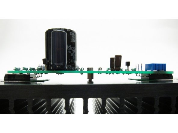
Sit back and take some time to admire the work you've done to date
-
Check that under the PCB there are no leads touching the heatsink (which is grounded)
-
-
-
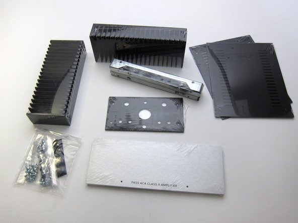
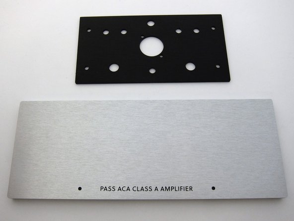
Check you have all the bits. These photos show the front panel without power switch.
-
First image: Chassis contents
-
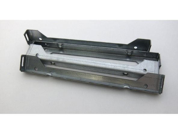
Second image: Heatsink rails
-
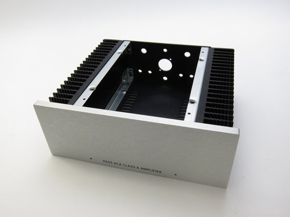
Third image: Front and rear panels
-
-
-
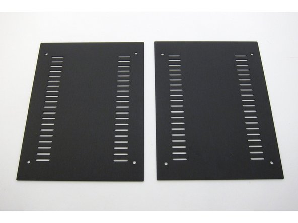
First image: Ventilated top and bottom panels
-
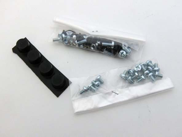
Second image: Hardware
-
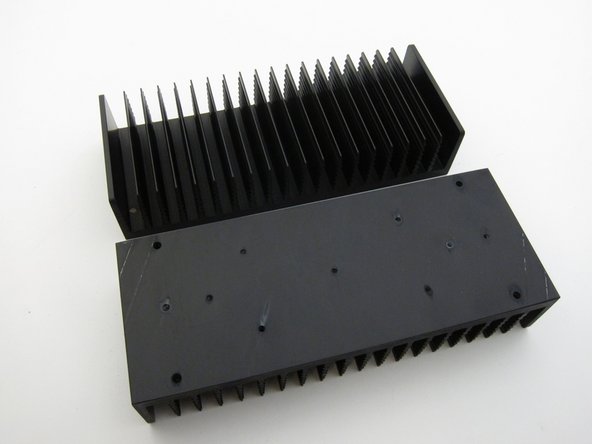
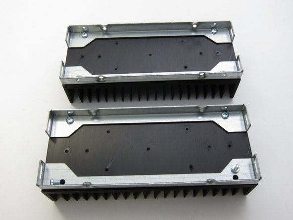
Third image: Heatsinks
-
-
-
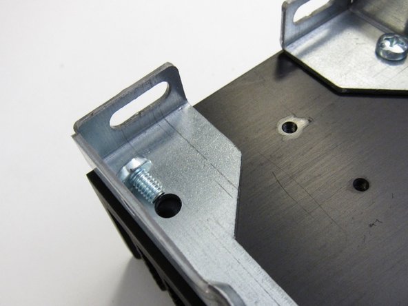
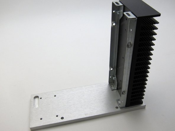
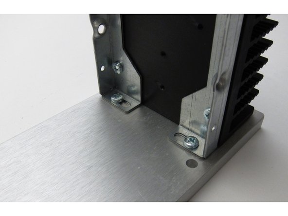
Attach the rails to the heatsinks
-
-
-
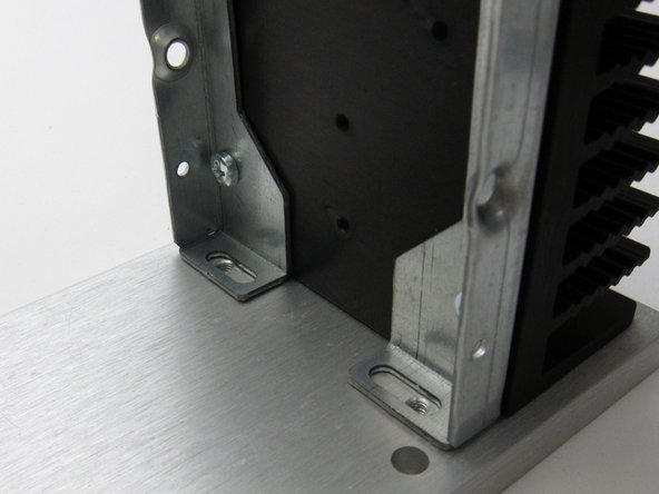
First image: Align slots with the holes in the front panel
-
Third image: Screws insert as shown
-
Please note that there is some intended slop in the bracket attachments. This can create slight alignment errors later when you are putting together the finishing touches on the chassis like screwing in the covers.
-
You might need to just tighten these up "fit tight" so you can wiggle them later, when you do a final alignment to get the screw holes in the covers to line up.
-
-
-
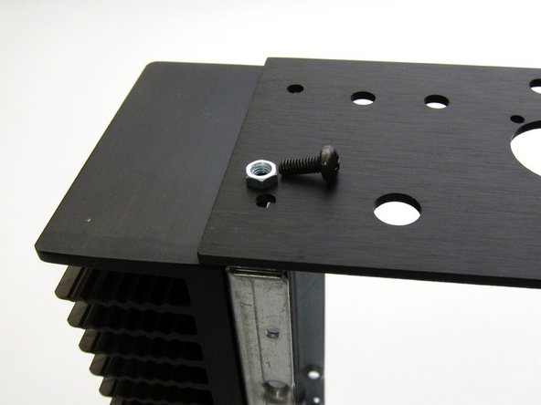
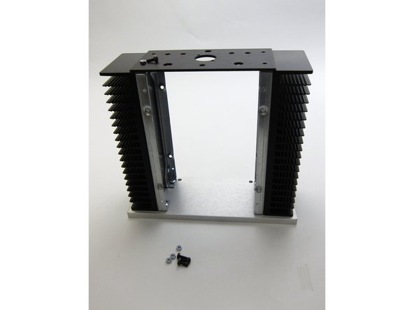
Rear panel attaches with nut and screw
-
-
-
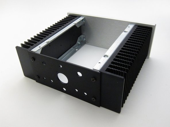
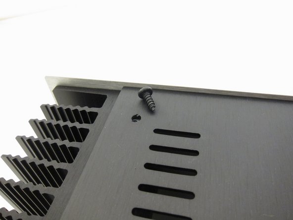
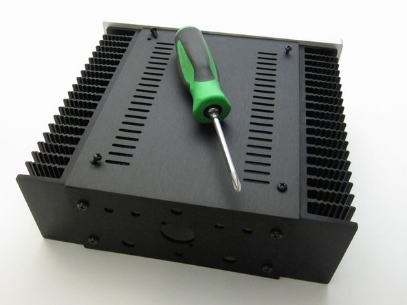
Sheet metal screws attach the top and bottom panels
-
-
-
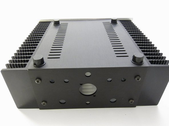
Feet are stick-on
-
-
-
Back panel hardware
-
-
-
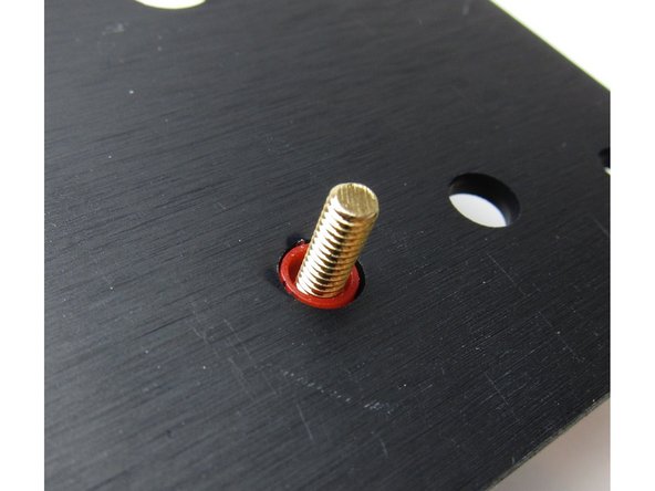
Viewing from the inside of the amplifier
-
First image: The colored shoulder washer goes on the outside, through the hole. This is to align the post so that no metal touches the chassis. BUT, on some posts things sit more flush if the round washer is on the outside and the shoulder is on the inside - either way is fine, do what aligns better.
-
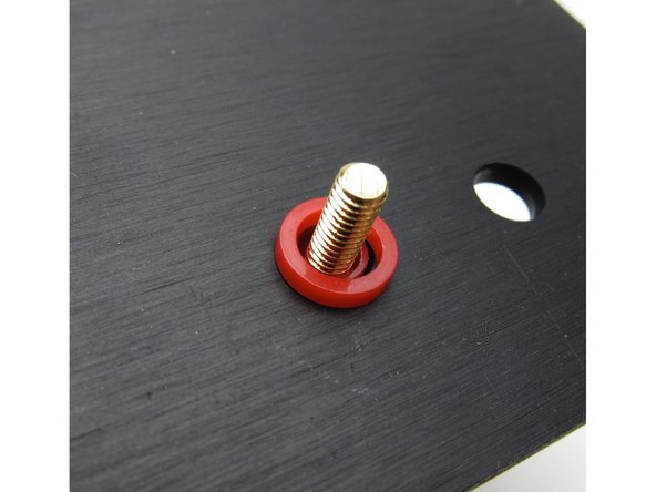
Second image: Then the other plastic washer
-
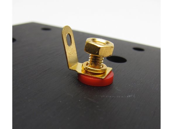
Third image: The metal tab sits upon the plastic, then lockwasher, and nut
-
-
-
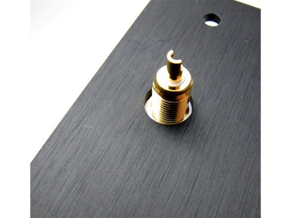
Align the hole in the post to be vertical.
-
-
-
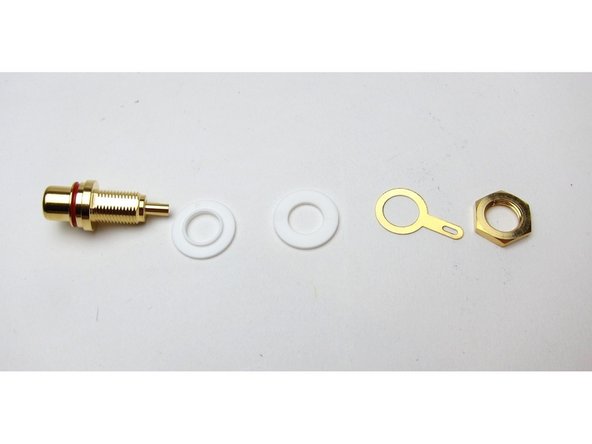
First image: RCA post hardware
-
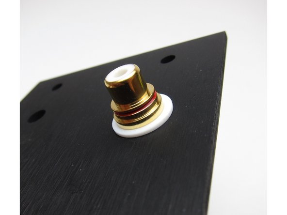
Second image: Again, viewing from the inside, the shoulder washer sits in the hole and keeps the metal of the RCA from touching the chassis
-
-
-
Interior view
-
Note raised bit (shoulder) on one RCA washers, this must face the inside of the hole to keep the assemble aligned and insulated properly
-
-
-
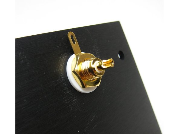
First image: split (lock) washer under the nut
-
Second image: outside of the chassis
-
Third image: Align so the tab is up, closer to the XLR
-
-
-
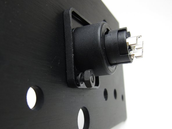
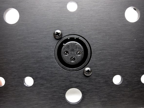
The XLR can mount inside or outside as you desire. Mounting inside will give a flush exterior.
-
-
-
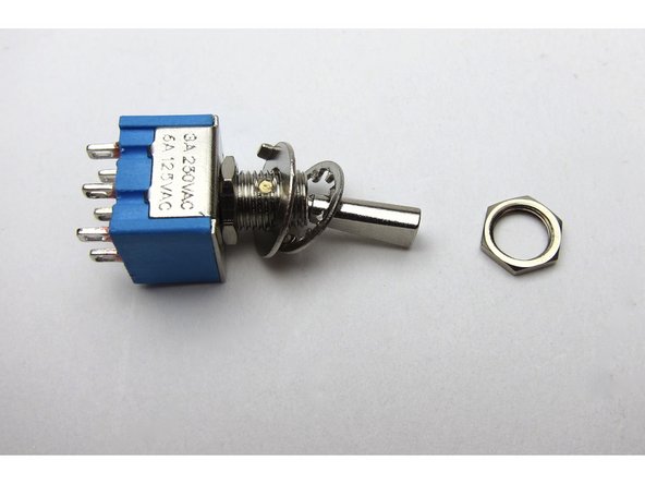
The rear switch is included in the kit as an "option" switch. This is a DIY project and you get to choose what that option is. Regardless of whether you are making an ACA with a front power switch or not, this toggle switch can optionally be configured by yourself to:
-
Switch the amp on and off
-
Switch between mono/stereo operation
-
Dim the LED
-
Etc
-
For simplicity in this guide which is focused on the "ACA with front power switch" configuration, from step 35 onwards, this toggle switch will be used to toggle between stereo and bridged mono operation when using RCA input. (XLR does not need the switch)
-
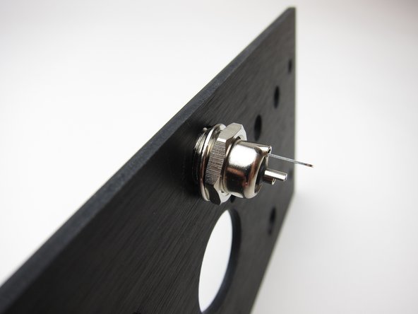
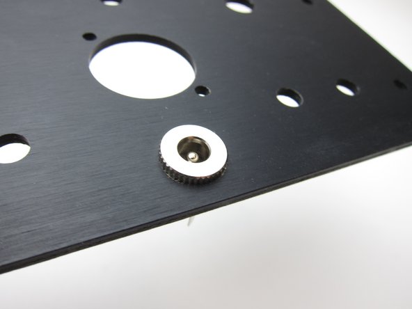
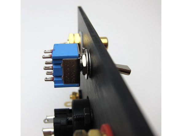
Look closely at the arrangement of washers and nuts. The rearmost nut adjusts switch depth, the big washer is keyed and the tab needs to point to the body of the switch, and then the lockwasher is up against the back panel. The last nut is for the outside of the back panel.
-
Mount as shown
-
-
-
This is the wiring diagram for batch 1 & 2. You have one of these batches if your kit shipped before Nov 20th 2018. If your kit shipped after this date (if so, your kit will include grey wire), please skip to the next step for the correct wiring diagram for your kit.
-
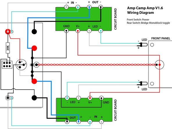
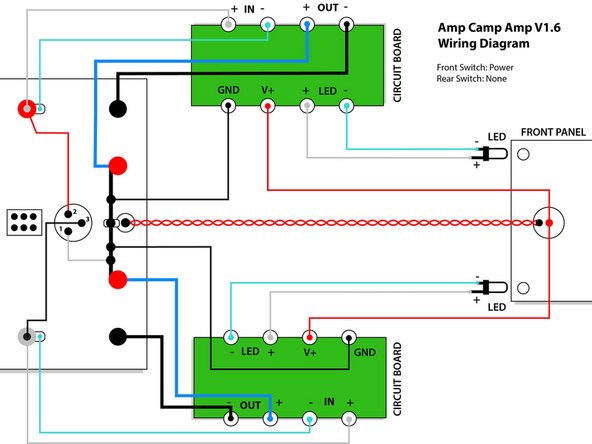
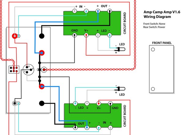
Please download the ACA V1.6 Batch 1 & 2 Wiring Diagram PDF, which shows 3 wiring options:
-
A) Front switch: Power; Rear switch: Bridge monoblock toggle
-
B) Front switch: Power; Rear switch: None
-
C) Front switch: None; Rear switch: Power
-
This guide mainly shows option A
-
-
-
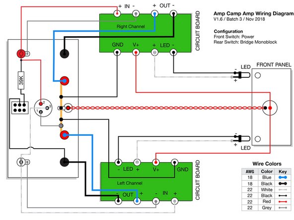
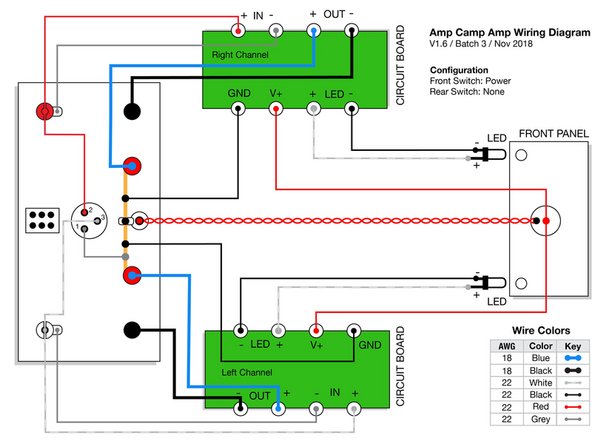
This is the wiring diagram for batch 3. You have batch 3 if your kit shipped after Nov 20th 2018 and your kit contains some grey wire.
-
Please download the ACA V1.6 Batch 3 Wiring Diagrams PDF and print out the correct wiring diagram for your amp.
-
Batch 3 includes one new color (grey). This allows for more unique color pairs and the ability to keep signal paths a similar color.
-
However, this means the wire colors in the pictures and videos in this guide will not match the wire you have received. Please be careful to always consult your wiring guide diagram, and do not assume the wire colors in the photos are correct for your kit.
-
We will update the photos and videos at some point in the future, please bear with us.
-
-
-
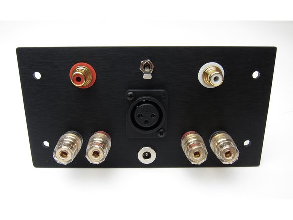
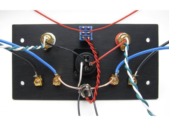
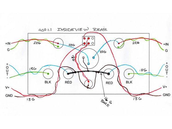
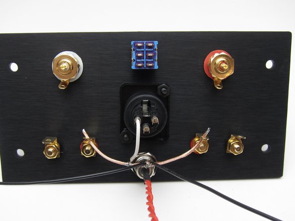
This shows everything attached to the back panel in the proper positions.
-
Yes, the red RCA is on the left when looking at the back - this is to have it on the proper side when the amp is facing forward.
-
XLR - this shows it mounted to the outside, but you may inside mount it as well if you desire, there's no benefit one way or the other.
-
Speaker jacks - REDs are mounted INBOARD, blacks to the outside
-
-
-
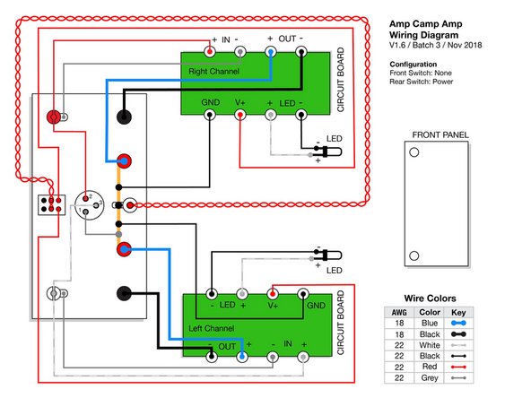
The image and diagram in this step is ONLY for people building the ACA with no front power switch.
-
With no front power switch, your wiring is simpler, and we will use the rear toggle switch for power only.
-
Please review the image and wiring diagram carefully. The DC jack is a bit ambiguous - to be clear, the red goes to the center pin and black to the outer tab.
-
The only significant difference between your build and the pictures shown in the rest of this guide are that your V+ wires will come from the rear switch, instead of the front switch.
-
If you want to bridge your amp this is no problem, please see step 46 of the ACA 1.5 build guide for how to make an external bridging connector.
-
If you are building your ACA with a front power switch, please ignore this step and its images entirely.
-
-
-
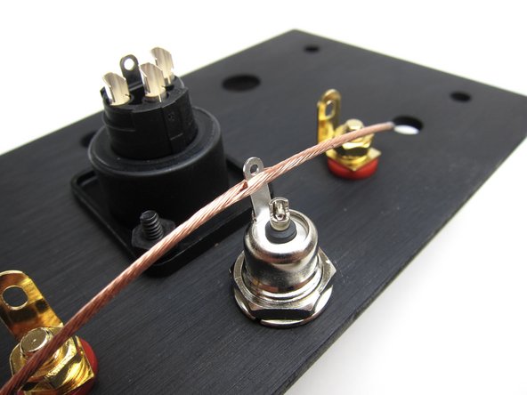
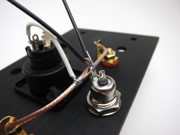
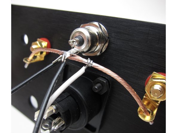
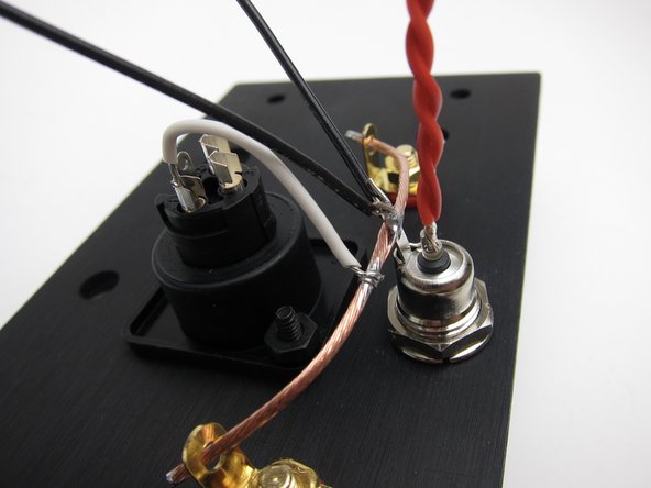
To create the ground buss cut a length from the heaviest gauge wire and strip the insulation off
-
The tab of the barrel connector should be "up". The wire may be soldered to the tab now, but don't solder it into the red (inboard) speaker jacks until you have the other speaker wires to the PCBs
-
Image 2 - Connect pin 1 of the XLR to the buss wire. Then connect 2 lengths of wire to the ground buss - these will connect to the power GND on the PCBs
-
Image 3 - from a different angle for clarity.
-
-
-
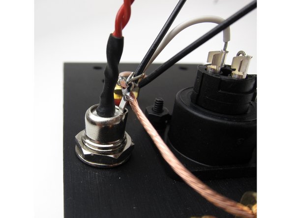
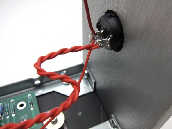
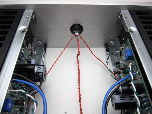
Make a twisted pair from red and attach to the center pin of the barrel connector. This will reach to the front panel switch.
-
Add a bit of heatshrink
-
-
-
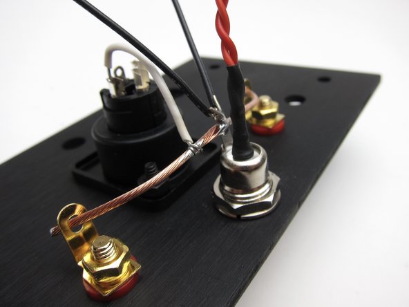
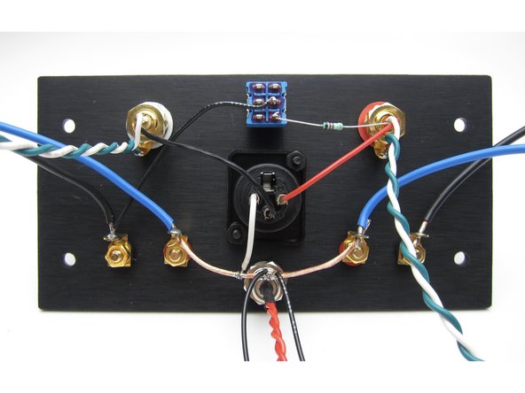
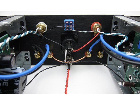
Image 1 - Panel so far.
-
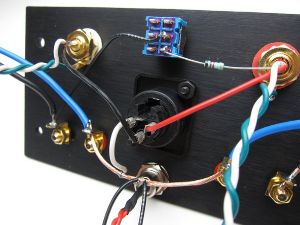
Image 2 & 3 - The rest of the connections, specifically;
-
XLR - Pin 2 is connected via red wire to the red RCA pin. Pin 3 is connected via black wire to the white RCA pin.
-
RCA - make a twisted pair of white and green long enough to reach the PCBs and attach white to the RCA pins and green to the tab.
-
Speaker Posts - using blue wire connect to the red (inboard) posts. Use black wire to connect to the black posts. These wires must be long enough to reach the PCBs. You may solder the speaker wire and the ground buss to the post now.
-
Stereo/Mono switch - black wire from the black speaker post of the white (left) channel to the center pin of the switch. Then connect the 39K resistor from the pin directly below the wire on the switch and insert the resistor lead into the pin of the red (right) channel RCA
-
WATCH THE VIDEO in the next step before proceeding. (It would be on this step but you can't have a step with videos and images together.)
-
-
-
Back panel wiring shown in this video. Please review before and after you proceed.
-
-
-
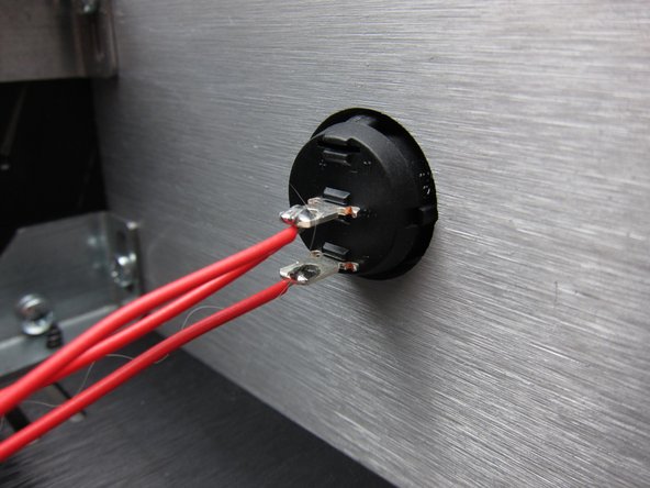
The front power switch is mounted to the panel from the front with the metal terminals in the center and down position.
-
Use your multimeter to verify the switch is functioning correctly before soldering. Be careful not to overheat the tabs during soldering which may melt the switch, in which case you'll need a replacement.
-
The bottom terminal receives power (V+) from the center pin of the barrel connector.
-
NOTE - yes, the wire from the barrel connector should be doubled up and twisted. These are the only photos that show these steps in-progress. :)
-
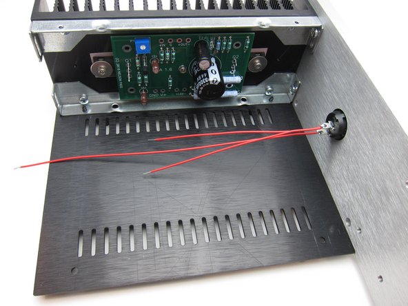
Image 2 shows the connections to the switch
-
Image 3 shows the connections from the center terminal of the switch to the PCB
-
See video in the next step for overview.
-
-
-
Video with overview of PCB and power wiring.
-
Shown are the connections from the top and bottom edges of the PCB as well as the power switch and barrel connector wiring.
-
-
-
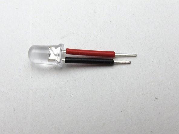
Your kit includes 4 LEDs. Some batches of ACA kits have clear looking LEDs, of which 2 are red and 2 are blue. If this is the case, you will need to test which is which.
-
Do not connect them to DC without a resistor in series. Connecting them directly to your 24V power supply will fry them instantly. Here's 3 methods to safely check the color:
-
(a) Use your multimeter's diode test mode
-
(b) Use a 1k resistor in series with a 9V battery or a 10k resistor in series with your 24V PSU
-
(c) Build your amp up without soldering the LED wires to the PCB, power it up, and try them in the live circuit (which itself has a 10k resistor in it to protect the LED)
-
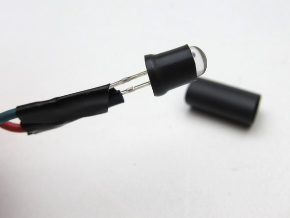
First take some left-over insulation from stripping your other wires and add it to the legs
-
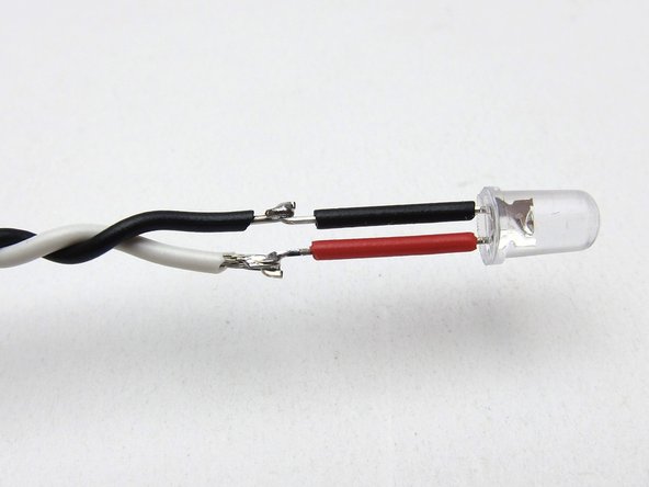
Then attach the wires. Long lead to +ve (shown as white wire), short lead to -ve (shown as black wire).
-
Tip: Cut the short lead and its insulation even shorter. That way the exposed part of the leads aren't opposite each other and can never touch.
-
-
-
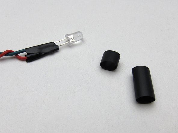
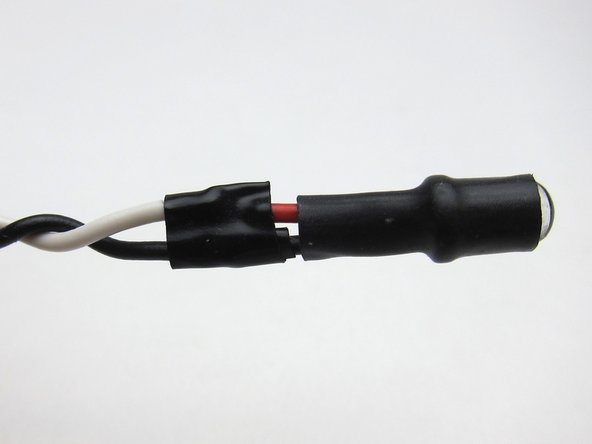
Your kit includes heatshrink that is pliable when warm and should nicely seat the LED in the hole in the front panel.
-
We have discovered there can be quite some variability in the thickness (and malleability) of the heatshrink used between batches. Use 1 or 2 layers as you feel works best for you.
-
Take an inch and cover the leads, flange, and half the body.
-
So that it stays in place, you may need to use some insulation or similar malleable material to create a shim. Optionally, heatshrink another 3mm piece on the head of the LED (some builders have reported this makes it too thick to insert).
-
You may need to use a little creative "DIY" here. Do what works best for you.
-
-
-
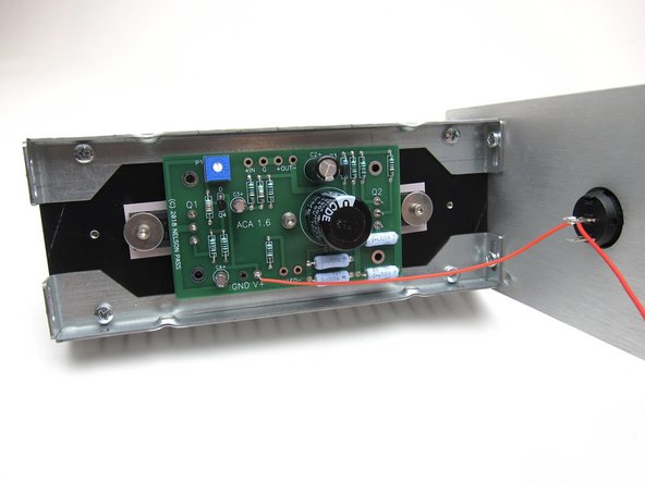
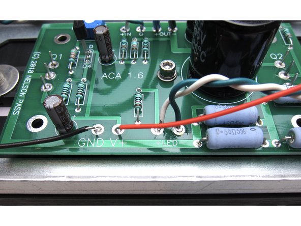
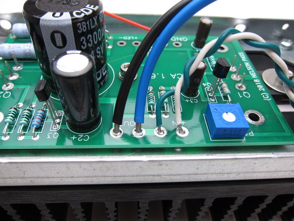
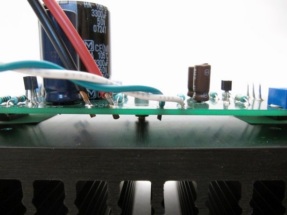
In the first photo you can see the power connections from the circuit board power and LED on the bottom edge,
-
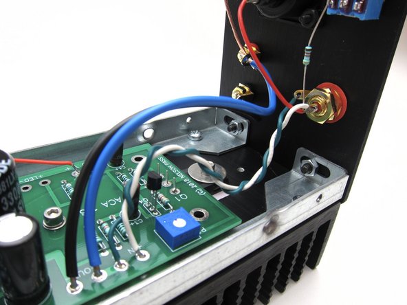
Photo 2 and 3 show input (from RCA) and wiring to speaker posts on the top edge.
-
-
-
Since many wire connections need to be soldered from the top of the PCB, strip the insulation and trim so it sticks through only 1-2mm. Make sure it does not touch the heatsink!
-
-
-
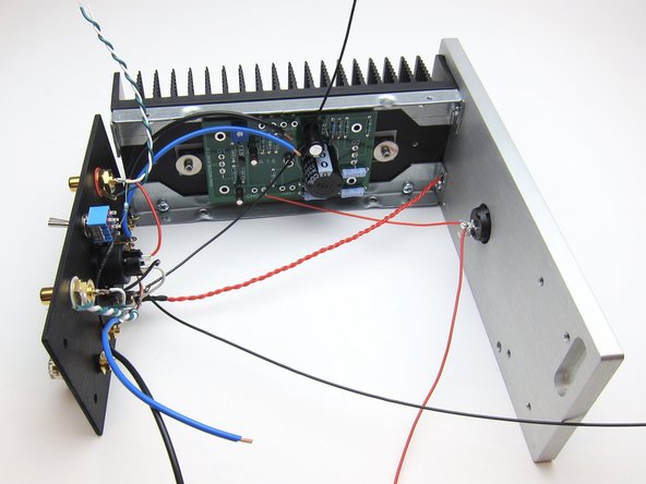
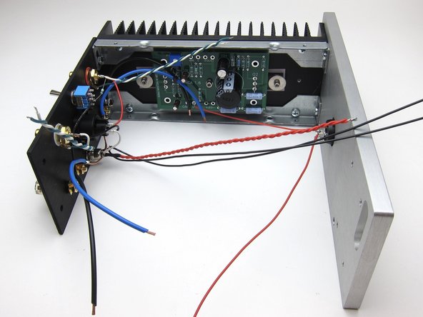
With the previous steps completed it's now time to start bolting it all together.
-
Mechanically, start with one of the PCB/heatsink assemblies and attach to the front panel. Then secure the back panel to the same heatsink assembly.
-
In this configuration try to get as many connections completed as possible, it will get more difficult when the 2nd heatsink is attached.
-
If you have a wire that's too long, you can trim or put a bend or two into it to take up the slack. This will also act as a stress relief on the wire and solder connection.
-
-
-
Final wiring should look like these photos.
-
-
-
This video shows the wiring of the completed amp
-
-
-
Video covering power up, connections and normal operations. Only one speaker shown because I can't fit two on my table.
-
The quiet turn-on noise is heard, as well as the small turn-off thump. This is expected behaviour from this particular minimalist circuit design. If you're really interested, there's a good thread about this topic brewing here.
-
Music used - Jan Johansson - Visa från Utanmyra https://www.youtube.com/watch?v=t2D5HlKL...
-
-
-
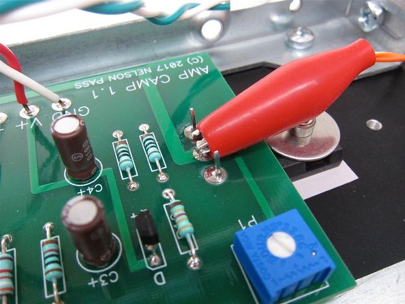
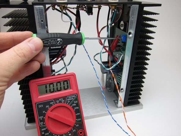
Setting the DC balance is very easy and the same for the 1.6 and 1.1
-
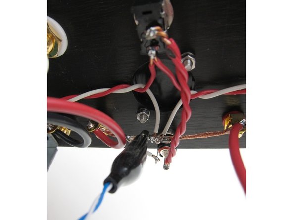
First image: Connect your DMM red lead to pin 2 of Q1
-
Second image: And the DMM black lead to ground. The buss is a perfectly good place to attach.
-
Buying clip leads for your DMM is not necessary for this job, but it does make many tasks much easier. :)
-
-
-
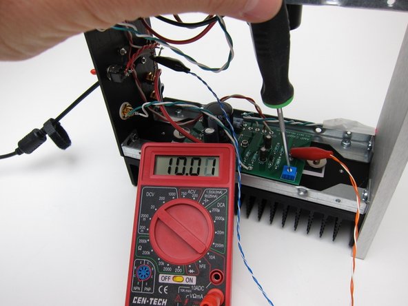
Set your meter to DC volts, use the 20vdc range if your meter is not auto-ranging. If using 24v PSU, set meter to 200vdc.
-
If using 19v PSU Adjust the pot in small steps to get 10v. A few tenths off in either direction is nothing to worry about. If you are using the 24V power supply, adjust the pot to get 12V.
-
The changes in voltage will lag behind the pot movement, almost in slow motion - this is normal. Small steps, wait a bit to let the voltage catch up, adjust a bit more, wait, etc...
-
You don't need to remove both the top and the bottom panels to make adjustments, however it's super easy to get to everything if you do.
-
-
-
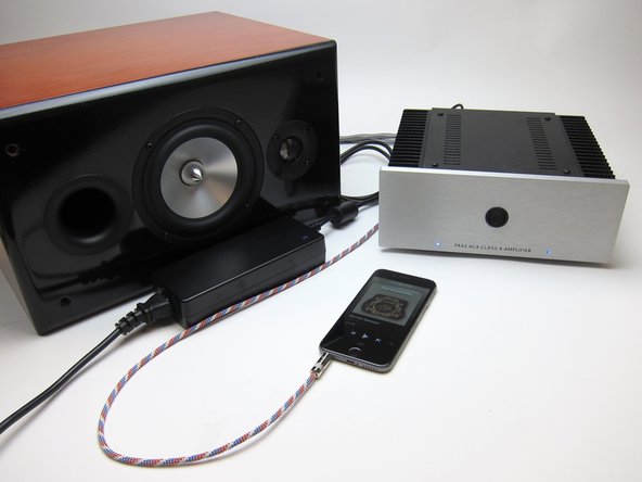
The ACA 1.6 is a fantastic stereo amplifier. Connections for proper use are as follows;
-
RCA inputs - Connect your source (Preamp, Phone. DAC, CD player with variable outputs, etc...) to the RCA jacks.
-
Stereo/Mono switch - should be DOWN for Stereo operation.
-
Speakers - Connect your speakers to the speaker posts as shown
-
Power - The PSU must be attached to the barrel connector and plugged in.
-
-
-
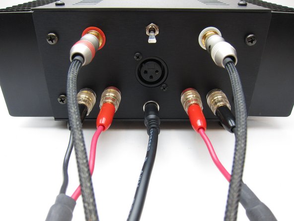
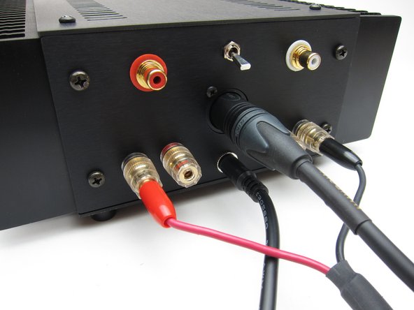
If using a source that has XLR cables, plug the XLR into the jack, and wire the speakers as shown.
-
Stereo/Mono switch in the DOWN position. (That switch is only used for RCA input)
-
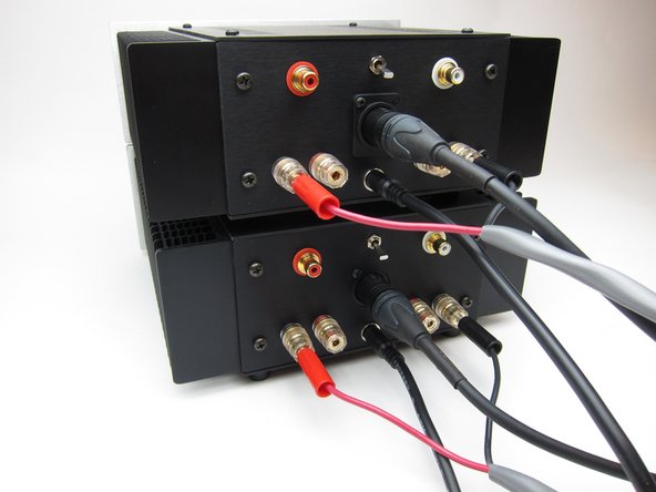
Regardless of how you wire for bridged operation, you'll need two ACAs for stereo now.
-
Please see the ACA Operation Modes document for more information about stereo, balanced, bridged and parallel operation.
-
-
-
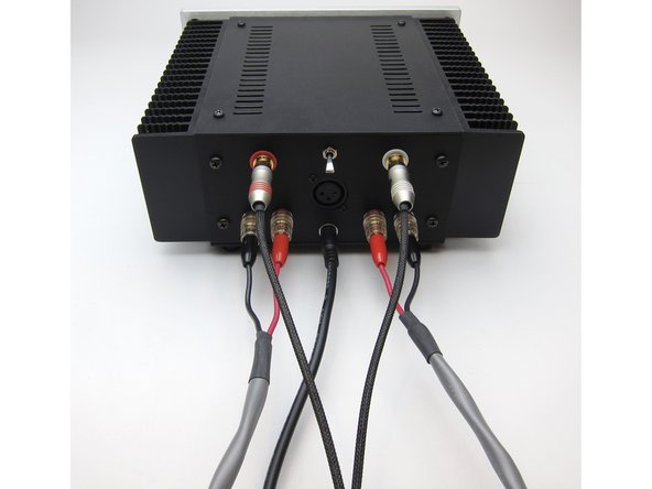
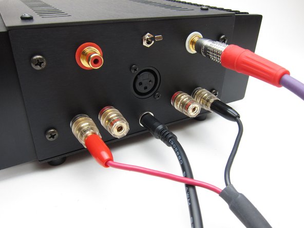
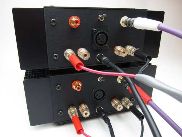
RCA input mono operation;
-
Connect RCA input to the white RCA.
-
Stereo/Mono switch in the UP position.
-
Connect speakers as shown.
-
-
-
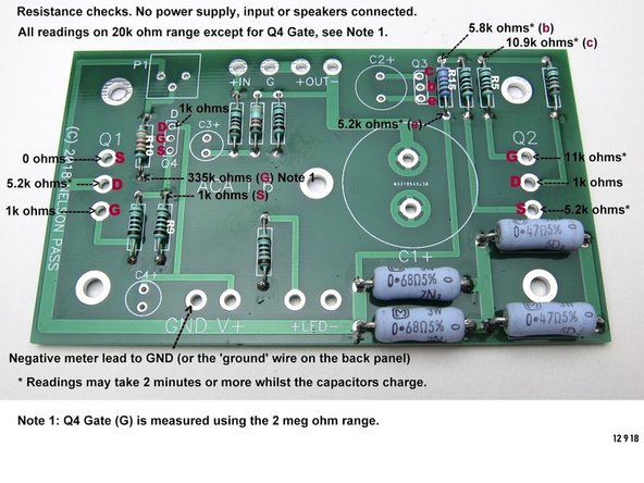
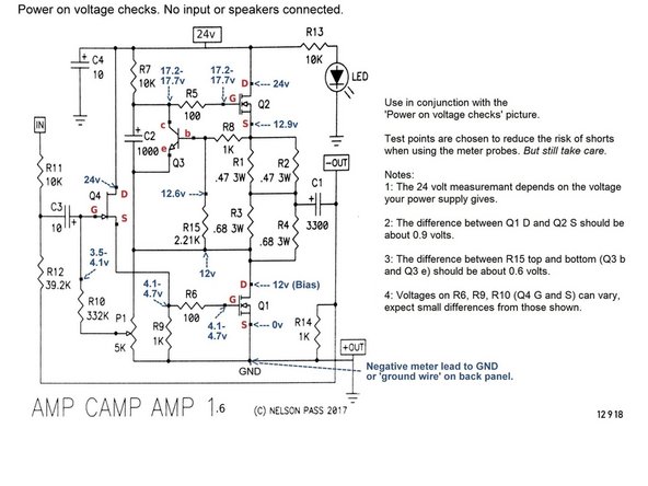
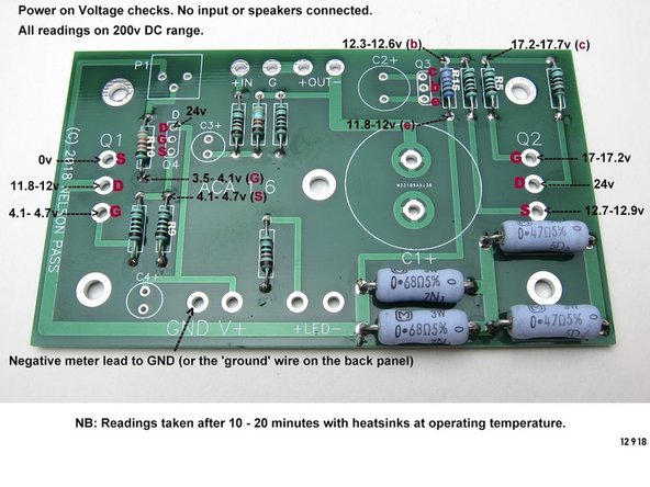
These annotated photos and schematic have some simple checks you can do with your Multimeter in case you have issues with your build.
-
Please note, most people having issues have found it to be some combination of soldering - a bad or cold joint, no solder, or a solder bridge.
-
That said, check all components to be in the proper location, make sure things are wired correctly, and make sure all components are installed.
-
More troubleshooting insights... etc etc, look at the notes on the images for more info until this section can be fleshed out.
-
-
-
Discuss your build and ask for help about anything at all in the ACA 1.6 Build Guide Thread
-
Upload photos of your finished product and talk about everything else in the Amp Camp Amp General Discussion Thread
-


We hope you enjoyed the guide! Please discuss your build, ask for help, upload photos and generally join in the diyAudio community discussion threads listed above!
We hope you enjoyed the guide! Please discuss your build, ask for help, upload photos and generally join in the diyAudio community discussion threads listed above!
Cancel: I did not complete this guide.
31 other people completed this guide.