
Introduction
The Iron Pre project is intended for intermediate to advanced DIYers. There is no full kit, and builders are required to choose and source many of their own parts appropriately.
This is not a complete instruction manual. This guide provides an overview of a typical Iron Pre assembly, and each builder will have a number of choices to make that are not covered in this guide.
This guide focuses on stuffing and testing the PCBs, but also provides limited instruction for overall assembly along with tips and tricks for the successful build of a pre-amplifier.
Pictures of the full build including the chassis and all wiring are provided for inspiration. Many builders have their own preferences for layouts and wiring.
Some of the parts shown in this guide will likely vary in appearance from your choices.
The build in this guide includes the Modushop chassis designed for the Iron Pre along with the 2021 version of the Iron Pre boards. It is important to note that the 2023 boards are slightly different, and notes of the differences will be provided as necessary.
Read this guide several times and print out all supporting documents including the board layouts and schematics before beginning your project.
For additional assistance and inspiration, visit the forum .... (Link)
-
-
WARNING Mains powered devices contain potentially lethal hazards or can become lethal hazards which may result in death or serious injury.
-
WARNING Ensure you fully understand all relevant electrical codes, regulations, and requirements for your area and understand electrical safety practices before attempting to build this project.
-
WARNING Do not attempt to build any mains powered device, including the Iron Pre, unless you understand how to do so safely. By building this project, you accept all liability.
-
-
-
The first section of the guide (Steps 3-11) covers stuffing all the components for the main Iron Pre Boards.
-
The second section of the guide (Steps 12-15) covers the build and installation of the twister board for input selection.
-
The third section of the guide (Steps 16-24) provides inspiration and examples of how you can install your Iron Pre into a chassis along with instruction for the final tests and settings to be performed.
-
Steps 25-30 Provide inspiration and supporting documentation
-
-
-
The Iron Pre PCB can be completely assembled as a unit. Some builders may choose to assemble their boards in sections based on functionality. This section of the guide shows the full assembly of the PCB.
-
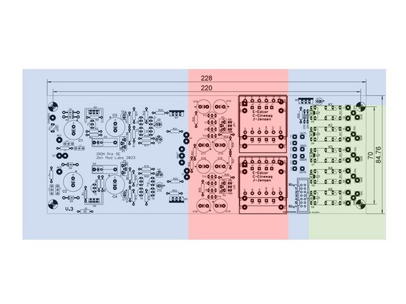
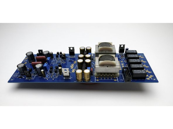
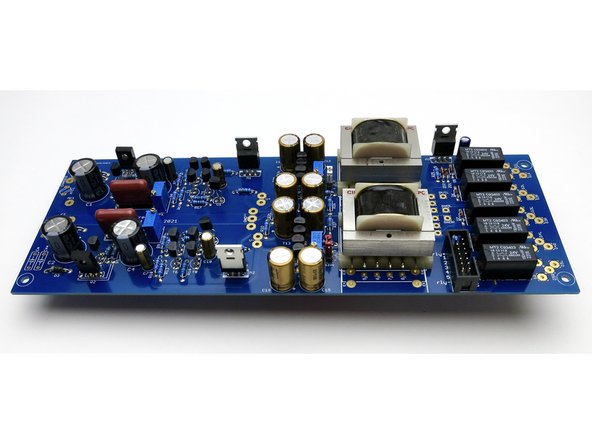
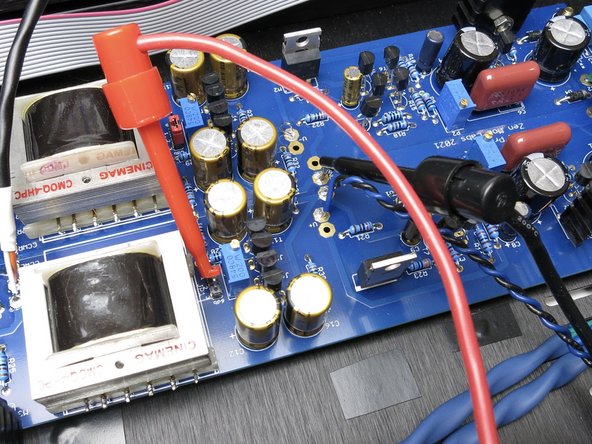
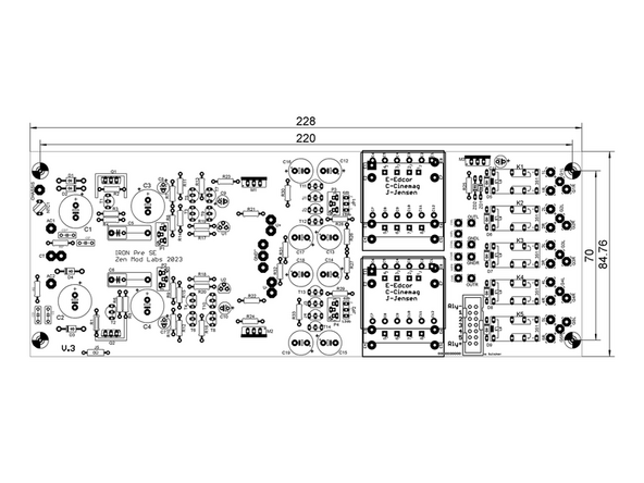
Image 1 - The blue section of the board is the power supply (aka the Good Gemini Regulator). The red section of the board is the buffer and transformer section. The green section of the board is dedicated to input and outputs along with switching.
-
It is wise to stuff the PCB following the typical practice of installing the parts from shortest to tallest by section while carefully following the schematics to ensure proper parts placement.
-
Before beginning assembly, it is wise to identify and test all parts prior to installation. It is particularly wise to use a transistor tester to separate and label all of your active devices. To the naked eye, many parts look identical, and the markings may be difficult to discern even with magnification.
-
-
-
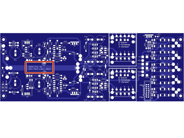
Begin with ensuring that you identify your PCB. Your PCB will be either a 2021 or 2023 board.
-
Image 1 - This is a 2021 Board
-
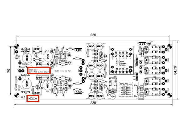
Image 2 - This is a 2023 Board
-
There is one additional jumper position on the 2023 board. If your are using the Twister board and a mechanical switch to change your inputs, install the jumper.
-
If you are using another system for switching your inputs, follow the schematics and instructions from the system you will be using and choose accordingly.
-
-
-
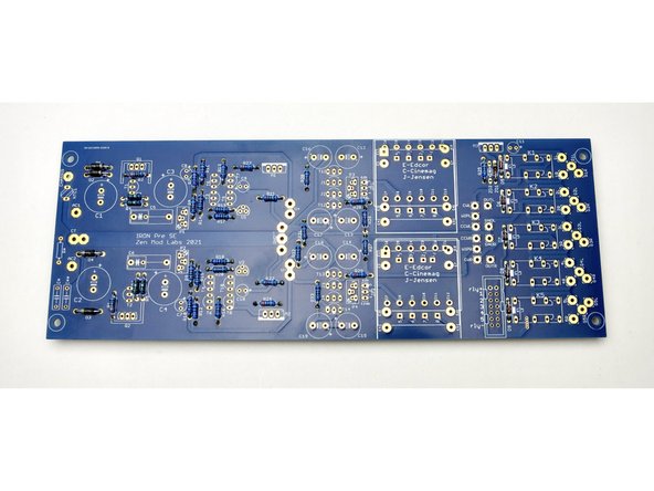
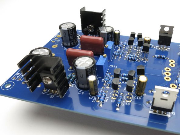
Photo 1 - Start with the shortest components.
-
See the schematic for the proper values for ZD1 and ZD2 based upon your choice of 12V or 24V relays.
-
Install all the resistors and diodes.
-
Note to builders - whichever attenuator you choose, take care of choosing Rin of buffer at least 10* that; meaning - input gate shunt resistor value changing accordingly for Iron Pre SE - R26 and R27; for Iron Pre (Bal) - R27, R28 or just solder 470K and be done
-
Be sure to check all resistor values before installation.
-
Be sure to check the orienation of all diodes.
-
-
-
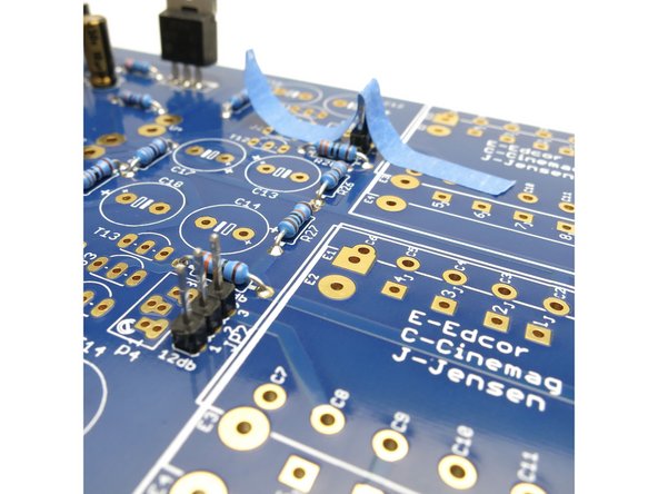
Photo 1 - It is extremely helpful to tape down the jumper headers before soldering. Make sure they are flat and touching the PCB.
-
Photo 2 - When installing the transistors, be sure to reference the schematic. There are a number of TO-92 package transistors. Identify them and sort them properly. Align the flat of the transistor with the flat drawn on the silkscreen.
-
-
-
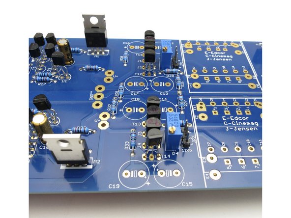
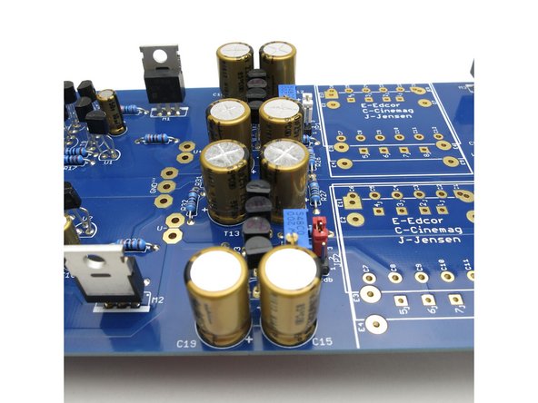
Continue to install all of the components from smallest to largest.
-
Be sure to double check the orientation of ALL the electrolytic capacitors against the schematic and the silkscreen.
-
Ensure that Q1, Q2 are clearly identified before installation.
-
Ensure that M1, M2, and M3 are clearly identified before installation.
-
-
-
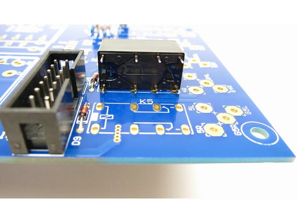
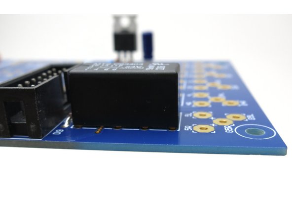
Photo 1 - The relays can only be installed one way. Ensure all pins line up. If any pins are bent, realign them to match the holes in the PCB.
-
Photo 2 - Ensure that all pins are inserted into the PCB holes, and that the relay sits flat against the board.
-
Photo 3 - A great way to hold the relays in place while soldering the underside of the board is with a piece of tape.
-
-
-
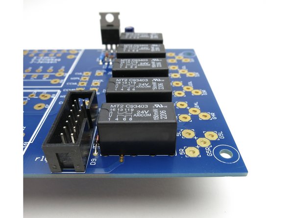
Photo 1 - Note the proper orientation of the box header. The notch lines up with the silkscreen image. This is critical when using an indexed cable and header.
-
Photo 2 - All relays installed.
-
-
-
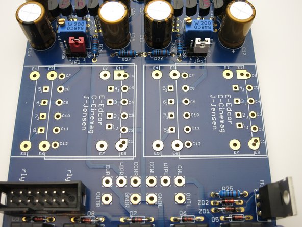
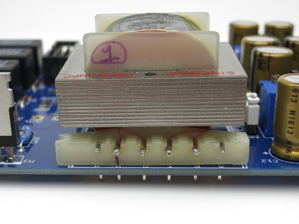
Photo 1 - The Iron Pre boards are designed for CineMag, Jensen, or Edcor transformers. The pads for each are clearly marked with C, J, or E respectively.
-
Check your transformer's data sheet to be sure you can find Pin 1. For the CineMag transformers provided with Iron Pre kits, pins 1 and 2 are noticeably closer together than all the other pins.
-
Photo 2 - Install the transformers ensuring a snug fit. Some gentle bending of the pins may be necessary. If gentle bending is required, make very small changes ensuring that you do not break the pins.
-
-
-
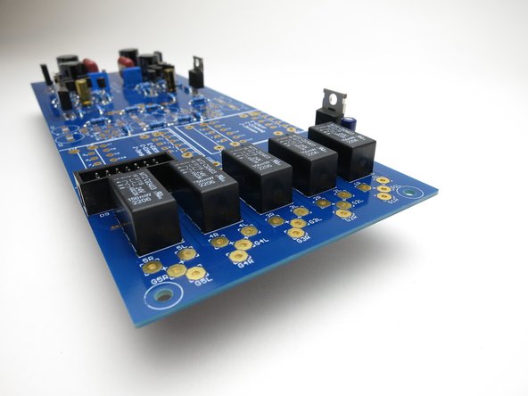
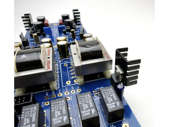
Photo 1 - Q1 and Q2 require small heatsinks. The parts do not need to be electrically isolated from the heatsinks, but it cannot hurt to use a mica insulator and some thermal compound or a piece of Keratherm or similar. The direction/orientation of the heatsinks is not critical.
-
Photo 2 - If you are using 12V relays, install a heatsink on Q3. If you are using 24V relays a heatsink is optional.
-
Photo 3 - Congratulations!
-
-
-
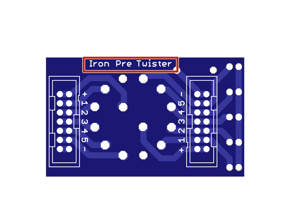
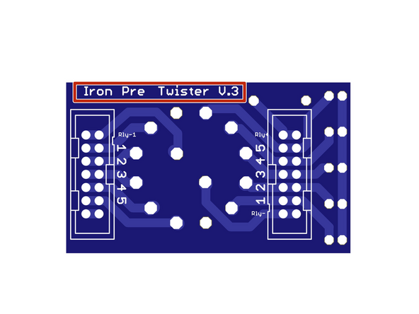
Be sure that you have the correct twister board.
-
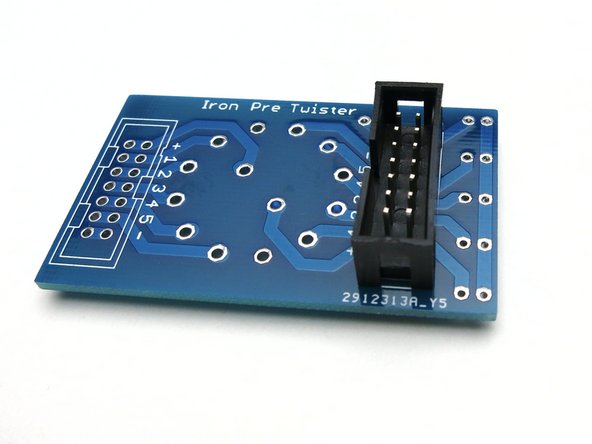
Image 1 - This is the twister board that mates with the 2021 Iron Pre Main Boards
-
Image 2 - This is the twister board that mates with the 2023 Iron Pre Main Boards
-
This side of the board faces the interior of the chassis. Commonly available 7x2 box headers fit perfectly to this side of the board.
-
-
-
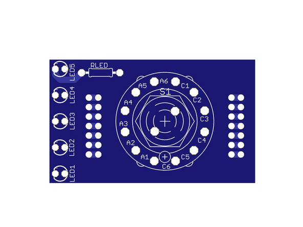
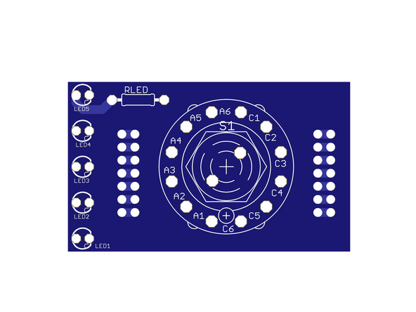
Image 1 - This is the side facing the front of the chassis for the 2021 Twister board
-
Image 2 - This is the side facing the front of the chassis for the 2023 Twister board.
-
Note the differences in how the LEDs are marked on the silkscreen. Pay particular attention to the 'C' and the flat side of the LEDs on the silkscreens noting the cathode of the LED. The orientation of the LEDs is opposing for the two boards. Be sure you triple check before soldering.
-
The Twister board is designed to accept a Lorlin CK1060 switch. The switch mounts to this side. Take note of the crosshairs above C6 on the silkscreen. This will match with the alignment nub on the recommended Lorlin switch.
-
-
-
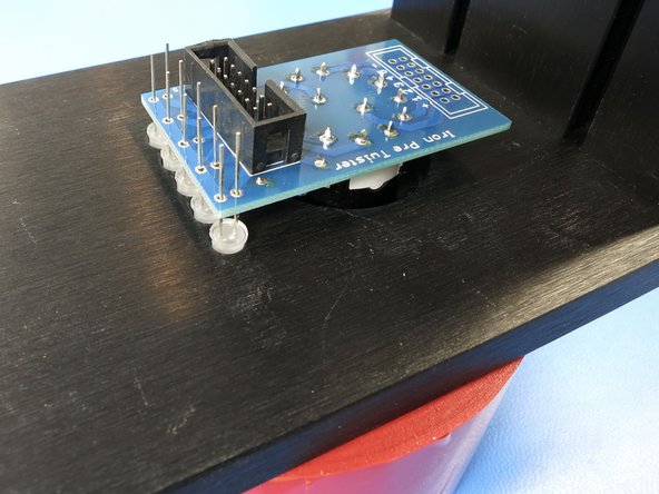
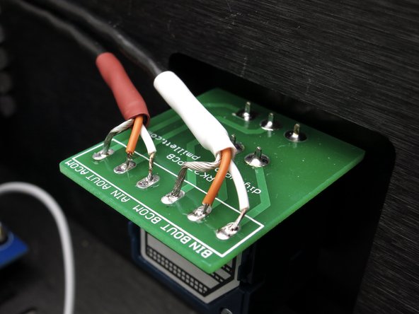
Photo 1 - Install the header noting the alignment of the indexing notch. Only one header is required for the Iron Pre SE. It should be installed on the side of the board closest to the LEDs.
-
Photo 2 - Install the input selector switch (recommended CK1060 shown).
-
Be sure to align the alignment nub on the switch to the crosshairs on the PCB above the marking C6.
-
Photo 2 - Install a current limiting resistor based on your choice of LEDs to suit your taste. If you’re unsure, install the closest value you have to 15k ohms.
-
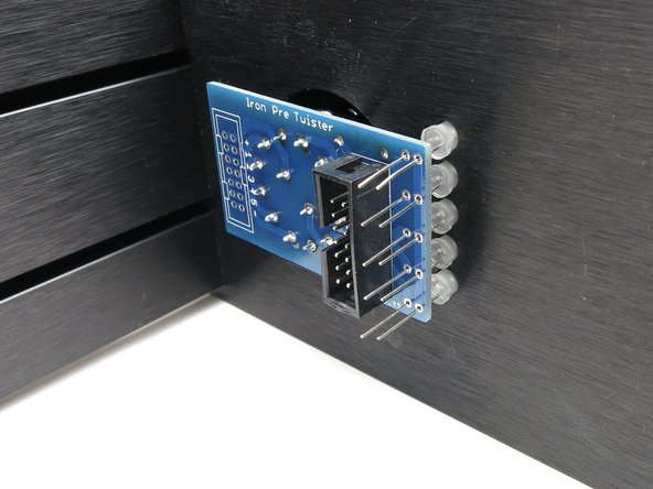
Photo 3 - Carefully insert the LEDs into the board, but do not solder them into place. Ensure the proper orientation of the LEDs. Fit the switch into the proper hole in your front panel and install the washer and nut. Note - The side panels may be installed to give the chassis stability.
-
-
-
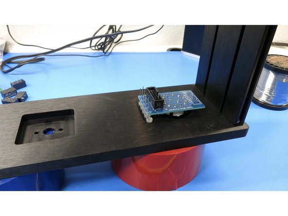
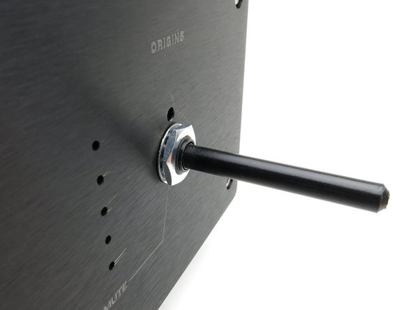
Place the front panel face down on a flat surface. Do not rest the chassis on the switch shaft; it will break. Be creative and rest the front panel on a roll of tape or use some other method to keep the weight off of the shaft. Gently tap the LEDs into their respective holes.
-
Solder the LEDs into place.
-
Obviously, you’ll need to trim the shaft to whatever length works best with your knobs.
-
-
-
Before assembling your chassis, installing your boards, and particularly before connecting anything to mains voltage it is assumed that you have the proper knowledge and/or are working under the direction of a trained electrician. Before assembling the chassis, it important to have done at least the following:
-
Verified the proper AC voltage output from your power transformer at full AC mains. A transformer with 18VAC secondaries or a 36VAC transformer with a Center Tap is recommended.
-
Planned your layout and sourced proper wiring and components meeting all safety requirements and ratings for your area.
-
WARNING All wiring is shown by example only. The wiring depicted may not be safe for your mains voltage or meet electrical standards or code in your area.
-
WARNING Mains powered devices contain potentially lethal hazards or can become lethal hazards which may result in death or serious injury.
-
WARNING Ensure you fully understand all relevant electrical codes, regulations, and requirements for your area and understand electrical safety practices before attempting to build this project.
-
WARNING Do not attempt to build any mains powered device, including the Iron Pre, unless you understand how to do so safely. By building this project, you accept all liability
-
-
-
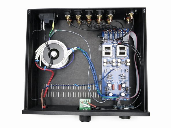
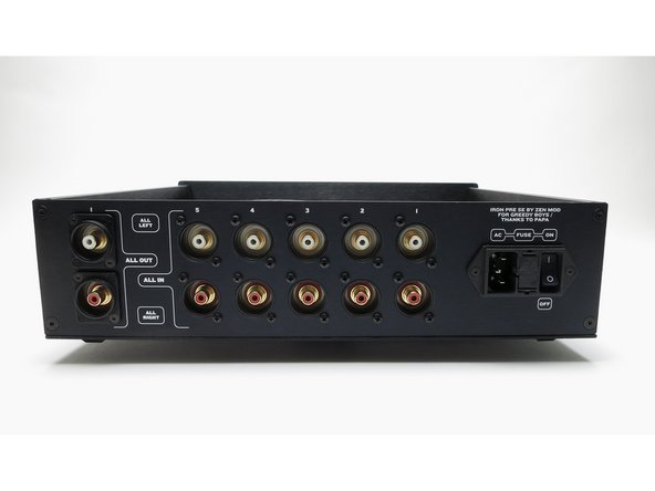
It is up to each individual to choose their own layout. The Iron Pre chassis is pre-drilled for the input selector, LED input indicators, volume pot, a power switch, LED power indicator, 5 inputs, one output, and a power inlet module.
-
Note that the transformer primaries and mains switch wiring is run along the left side of the chassis and that the wiring is tightly twisted. Transformer secondaries are tightly twisted and routed away from the volume control and signal wiring.
-
Note that signal wiring from the PCBs to the volume pot is routed carefully along the right side of the chassis.
-
Note that the input and output wiring is tidy and short.
-
-
-
Image 1 - This is a very basic wiring diagram.
-
It is absolutely critical that you understand mains voltage safety!
-
Fusing is not specifically shown in this wiring diagram. Choose a properly rated fuse, and wire/install it according to your area's codes and regulations.
-
-
-
This build uses a commonly available Alps RK27 "Blue Velvet" volume potentiometer along with a PCB. The wiring here is shown specifically for this combination. If you have chosen a different potentiometer, and if you are unsure how to mount or wire it, please ask for help in the forum.
-
Take note that each channel's wiring has a color-coded heatshrink. In this case, white is for left, red is for right.
-
-
-
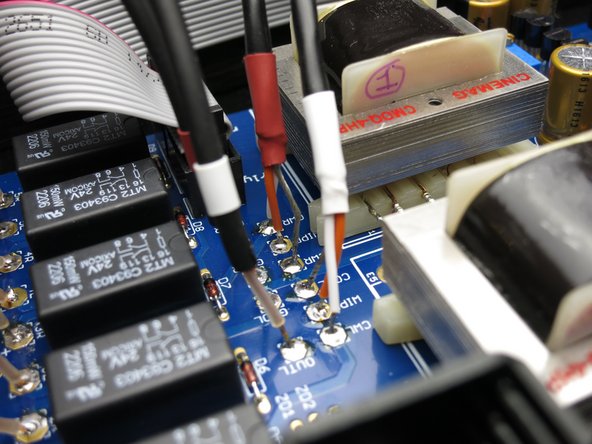
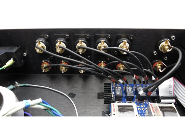
Photo 1 - Note the clean, tidy, and short input and output wiring. Up to five switched, single-ended inputs can be used.
-
Photo 2 - LED wiring for the power indicator. A skilled builder will place a current limiting resistor (where did you put it)...
-
-
-
It is recommended that the boards be completely stuffed and that all mains and internal AC voltage connections have been made in a proper and safe manner before proceeding with testing. Some builders prefer to test as they progress. In order to set the DC voltage and the DC offset, you must have at least the following completed:
-
The PSU and buffer sections of the boards are stuffed.
-
Proper AC voltage supply connected to the Iron Pre Main boards.
-
-
-
As an experienced DIYer, you'll likely have a variable transformer and/or a dim bulb tester. It is an excellent practice to ramp up the AC voltage slowly while watching the DC output and/or current limit the AC mains supply.
-
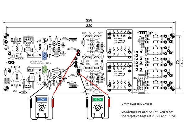
Power up / ramp up the AC voltage slowly while measuring the DC voltage from GND to V+ and GND to V-. If the DC voltage exceeds 20V before reaching full mains voltage STOP. Request assistance.
-
Image 1 - Once you have reached your full mains voltage without releasing the magic smoke. Slowly turn P1 and P2 until you reach the target voltages of -15V0 and +15V0
-
-
-
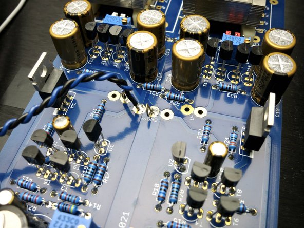
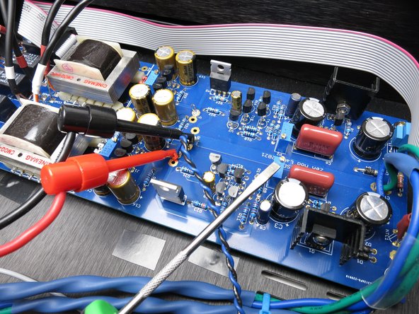
Photo 1 - It's very helpful to make a small loop from a cut-off resistor lead or small wire to have a place to clip your voltmeter.
-
Photo 2 - As per the diagram in the previous step, meter as shown for V+, and adjust the pot the screwdriver is pointing to.
-
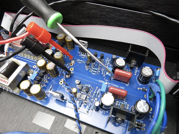
Photo 3 - Connections and potentiometer for V-. Note that on both rails the black meter probe remains connected to GND.
-
-
-
A short clip showing V+ being set.
-
-
-
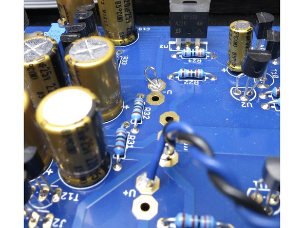
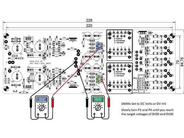
Measure between GND and the middle pin of each jumper.
-
Turn P3 and P4 until the voltage is 0V00 +- 0V01. If you cannot null the DC offset to +- 0V01 request assistance.
-
Install the jumper caps for your choice of gain.
-
Photo 2 - Connections shown to set R channel. Adjust potentiometer closest to the red probe. Black probe connected to GND at PSU taps.
-
-
-
Clip showing DC offset null procedure on R channel.
-
-
-
Install the cable from the main boards to the twister board
-
Check that the inputs switch properly. Full counter clockwise is mute. No LED should be lit for mute. Inputs one through five should be selected as you turn the input selector clockwise, and the LEDs should light accordingly.
-
Verify that all inputs work properly using a test signal or your favorite music in your test bench system.
-
-
-
Congratulations!
-
-
-
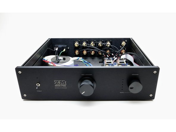
Your completed build may look something like this.
-
-
-
Image 1 - Parts Placement
-
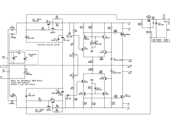
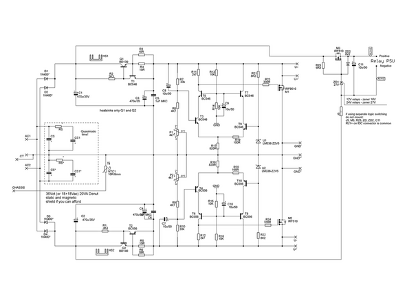
Image 2 - Power Supply Schematic
-
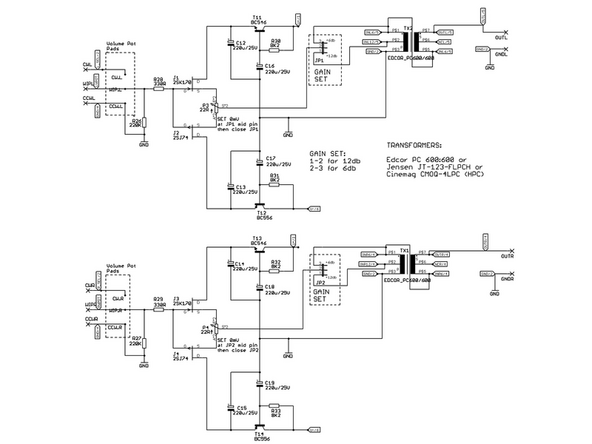
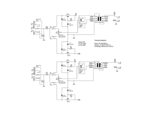
Image 3 - Buffer and Gain Schematic
-
Kits provided from the diyAudio store contain K370 JFETs vs. K170 JFETs.
-
-
-
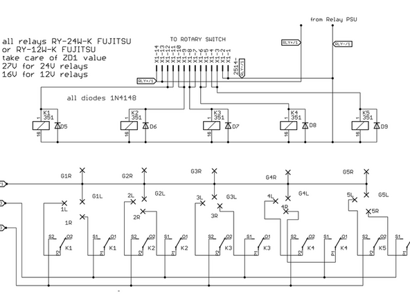
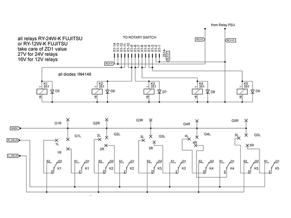
Image 1 - Input Switching Schematic
-
-
-
Image 1 - Parts Placement
-
Image 2 - Power Supply Schematic
-
Image 3 - Buffer and Gain Schematic
-
Kits provided from the diyAudio store contain K370 JFETs vs. K170 JFETs.
-
-
-
Image 1 - Input Switching Schematic
-
-
-
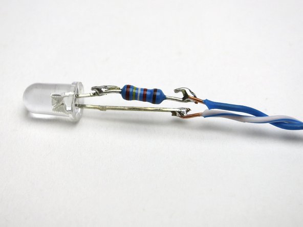
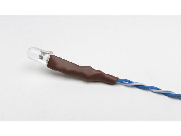
The LED for power indication needs a resistor. Anywhere between 15-30K will work, depending on how bright you want the light.
-
Add the resistor in line with either side, it doesn't matter which. In this photo it's on the cathode, indicated by the physical structure inside the lens being bigger, and the part that lights up.
-
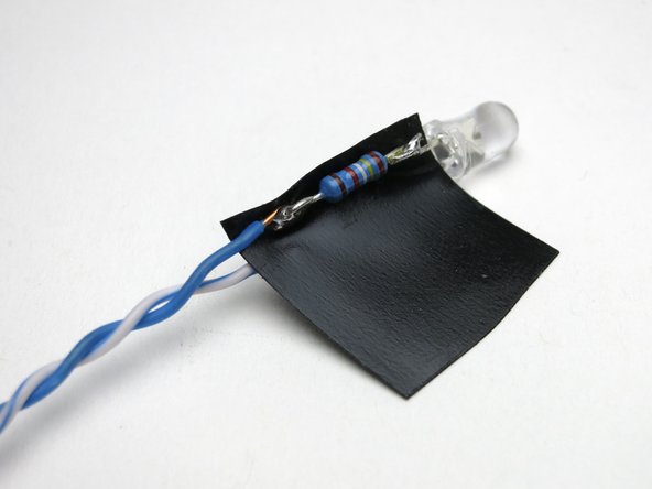
Insulate properly.
-


Cancel: I did not complete this guide.
3 other people completed this guide.