
Introduction
Wayne's
Headphone
Amplifier
Must
Make
Yourself
Yes, it's a silly name. But it's cute. And it explains a lot about it. So it stuck.
- Video of Wayne talking about the Whammy at BAF 2017: Wayne Colburn at BAF '17
- PCB available here: WHAMMY Headphone Amplifier – diyAudio Store
Given the explosion in the popularity of headphones, as well as the unbelievable amount of choice and variety in the market, it seemed that a simple and great-sounding headphone amp would be a great addition to the DIY community.
This one will drive any headphone you want to throw at it. Wayne wanted a headphone amp for his desk. This is the fruits of that idea. It’s made to be made in an afternoon or an evening and it has no adjustments, it’s going to have a high likelihood of success for the builders. :)
It's an all in one PCB, just wire the AC & fuse, input and output jacks. Add a selector switch if you like.
Class-A output stage with enough current to drive anything. It also makes a good linestage with about 14db of gain.
For more information see the WHAMMY build guide thread on diyAudio.
Video Overview
Wayne talking about the WHAMMY headphone amplifier at Burning Amp 2017
-
-
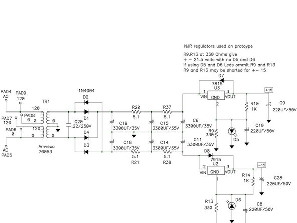
This is the schematic
-
-
-
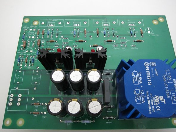
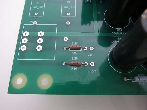
The green PCB shown here and used throughout this guide is a revision 3, the latest version, identifiable by the pads near the pot for the 2.2k resistors. Production versions in the diyAudio store are very slightly different in appearance as they are black. They are otherwise the same.
-
-
-
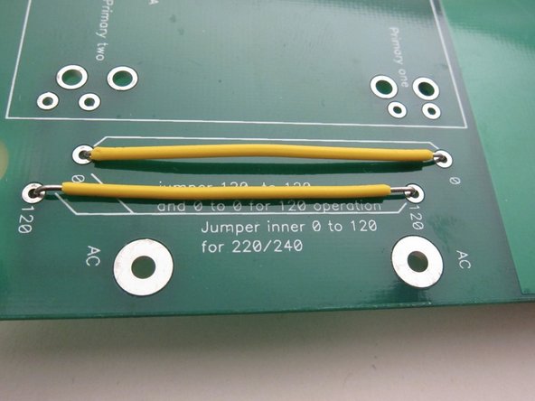
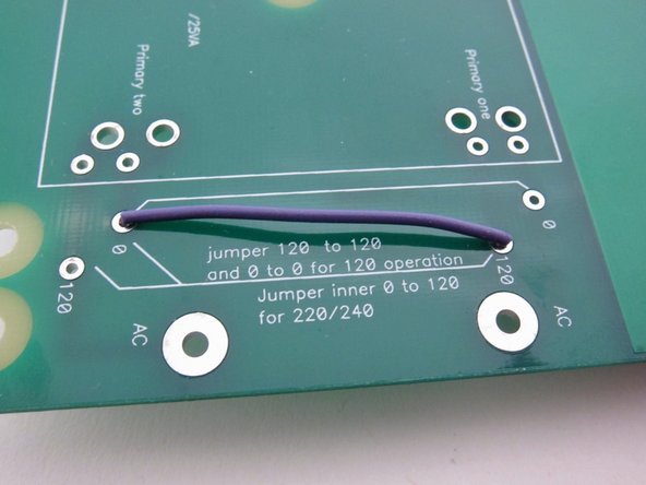
The transformer have dual primaries and can be used for 120VAC or 240VAC mains. There is room for jumpers on the PCB and they must be connected properly depending on your mains voltage. Instructions for the jumpers are written plainly on the PCB.
-
Yellow wires: 120VAC jumpers
-
Purple wire: 240VAC jumper
-
-
-
With the Hammond enclosure you can see that things get pretty tight. I used a small IEC inlet with integral fuse. I also wish I put the IEC more in the center of the back panel instrad of directly behind the transformer...
-
Note that the AC Live should be the lead that is fused, and some IEC sockets have fuses on the Live and Neutral, check with your country’s codes to see if having Neutral fused is acceptable.
-
Live should go to the lead winding of the primary which is the AC pad towards the middle of the PCB, and the Neutral to the trailing lead, the AC pad closer to the corner.
-
Safety earth is attached to the chassis via a screw and a star washer. If you add a power switch, switch the Live lead.
-
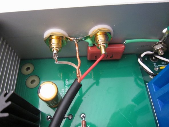
You can (sort of) see the screw and star washer used for safety earth in the second photo. The orange capacitor is attached to safety earth on one side and the ground tabs of the RCA jacks on the other. The RCA jacks are isolated from the chassis with their shoulder washers.
-
-
-
Print out the Schematic and have it in front of you at all times when soldering.
-
Making sure the PSU is behaving properly first is an integral part of a successful build. So it will be populated first.
-
This PSU requires some choices to be made, so DO NOT populate everything on the schematic. It will not work properly if you do. More about this in a few steps.
-
When working on any part of this project, print out the schematic and have it in front of you at all times.
-
-
-
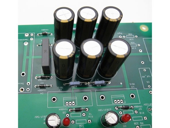
Start with the passive filtering - the rectifier diodes, the filter resistors, the grey snubber capacitor, and the tall filter capacitors.
-
Note that the big caps are polarized, and need to be on the PCB in the right direction or they will blow up. The + is noted on the PCB, and the + also has a square pad. + is indicated on the capacitor by the long lead, in addition, - is shown on the cap’s insulation.
-
At this time also stuff D7 and D8, they are protection diodes for the regulators and will be used in all configurations.
-
-
-
This PSU requires some choices to be made, so DO NOT populate everything on the schematic. It will not work properly if you do.
-
All configurations work beautifully and are very quiet.
-
I suggest that you build it with the LED voltage reference, and the bulk of the photos in the guide will show this.
-
The PCB has the ability to be wired to use the regulators in their most simple mode, to have a LED voltage reference added, or to have the voltage set by using a resistor voltage divider. This is to give builders a chance to use many different configurations to suit what parts and transformers that may have.
-
-
-
If you don’t have a specific other reason to do so, build this configuration.
-
This is the quietist configuration of the three, though not by all that much.
-
The LED is used to elevate the regulator off ground by it’s V fwd, and the cap is used to control the impedance of the diode at high frequency, making the whole circuit quieter.
-
Use a red LED to raise the voltage by about 1.8v more than the regulator, use orange, green or yellow for a few more tenths of a volt.
-
Do not use blue or white, they are 3.3v and very noisy when used as a voltage reference.
-
If you want to use one of these as a light for the front panel you may, but it would be better to attach a different LED and resistor to the V+ and ground output of the raw PSU.
-
Do not stuff R9, R10, R13, R14.
-
-
-
This is the simplest configuration, it uses the 78xx and 79xx regulators in their most simple configuration. R9 and R13 are jumpered in order for the regulators to see ground and nothing else is added.
-
Also note that the flat of the regulator is facing the line on the silkscreen. they are shown here for illustration. Heatsinks will be added to the regulators, do not run these without heatsinks.
-
Do not stuff D5, D6, C8, C10, R10, R14.
-
Jumper R9, R13.
-
-
-
Using resistors at positions R9,10 and R13, 14 and the capacitor, will set up a voltage divider across the reg setting the output voltage at 21.5 when using the suggested values.
-
Do not stuff D5, D6.
-
-
-
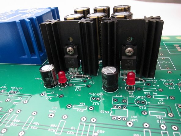
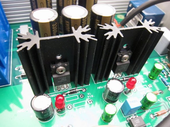
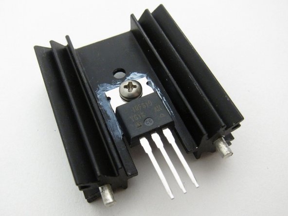
Install the regulators.
-
The heatsinks are soldered to the PCB, the pins do take some time to get hot enough to solder, because it's a heatsink...
-
The tabs that secure the heatsinks are not connected to anything electrically, they are only a mechanical connection. Because of this, you do not need insulators if your devices have metal tabs.
-
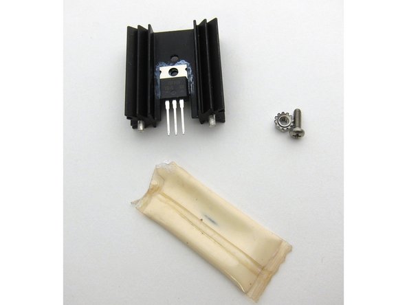
A think layer of heatsink compound is very helpful for thermal transfer. Less is more, you want the minimum possible to completely cover the interfacing surface.
-
Photo 1 - regulators mounted on heatsinks and installed. Photo 2 - another angle for clarity. Photo 3 - heatsink compound and screw/nut.
-
-
-
Plug in the transformer and power it on. The LEDs should light.
-
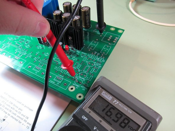
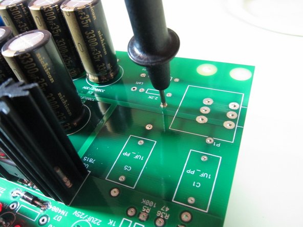
Place your meter to DC volts and measure the V+ rail between the ground pad near the pot and the square pad of capacitor C9. (Or both pads of C9, red on square and black on the round) This should read approximately +17V give or take a volt.
-
The square pad of C9 is a good place to test V+
-
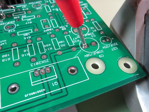
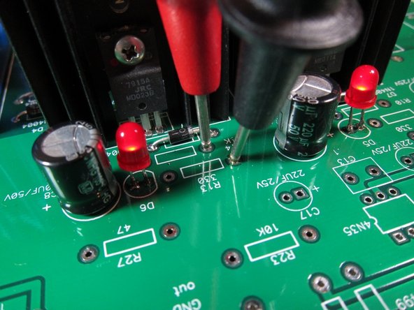
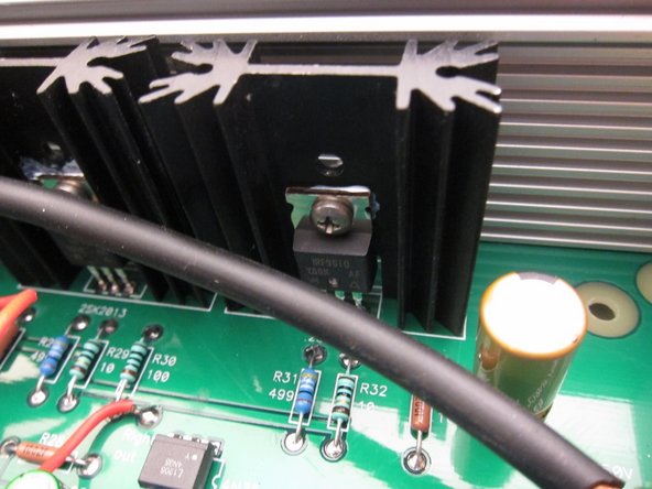
Measure V- with the black probe on R13 pad and red on the R14 pads as shown. Read -17V plus or minus a volt or two.
-
-
-
First photo: Measure V- with the black probe on R13 pad and red on the R14 pads as shown. Read -17V plus or minus a volt or two.
-
Second photo: Probe position for measuring V-
-
Why are the voltages not precise? Because there is no load on the regulators at all, and they have no current flowing through them to regulate. This is normal with the rest of the board unstuffed.
-
If the voltages measure good and there’s no smoke or shorts, move on to the next step!
-
-
-
Print out the Schematic and have it in front of you at all times when soldering!
-
-
-
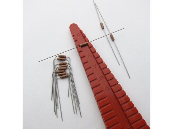
Although somewhat invalidated by the PSU being complete, the old advice of stuffing the smallest to the biggest components holds true. Start with the resistors.
-
All resistors have 0.5” lead spacing.
-
Please align the resistors in the same way - if banded put the brown band on the bottom or the right, and if the value is printed make sure you bend the leads so that the value is on top, and align to they read left to right or bottom to top. This will help troubleshooting later
-
-
-
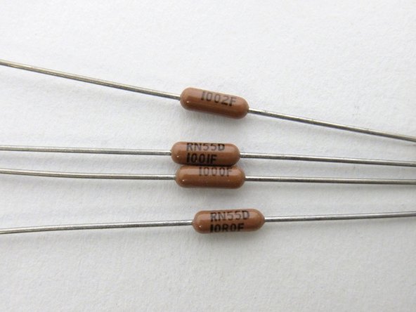
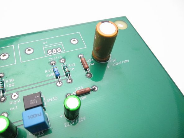
The Dale resistors have thier value printed on the side, the code is 3-digit + multiplier at values greater than 100ohm, and below 100ohm the "R" is the decimal. So, from top to bottom you see 10K (100+2 zeros, 10000ohm) 1K (100+1 zero, 1000ohm) 100 ohm (100+0 zeros, 100ohm) 10.0 ohm (10R0, 10.0 ohm)
-
Lead spacing for all small resistors is .5inch (12.7mm)
-
Bend the leads and align the Dale resistors so the value is facing up and readable.
-
-
-
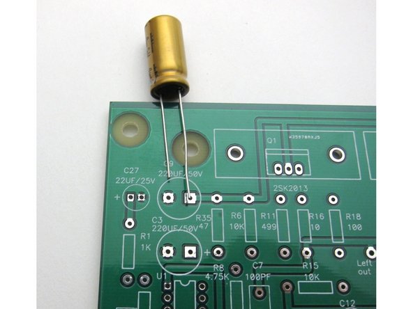
Remember that when using polarized capacitors to put the long lead (+) into the square pad.
-
Leave C2 and C7 empty. These are the place on the board for the compensation caps that didn't end up being necessary.
-
-
-
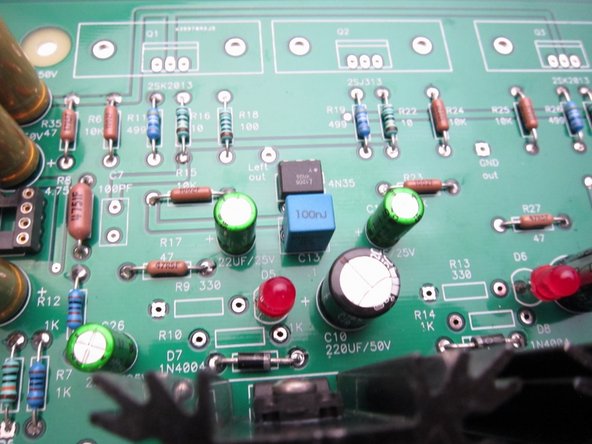
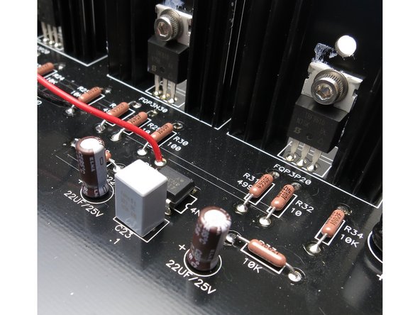
These images show the alignment of the 4N35 optocoupler.
-
The dot on the body of the optocoupler is placed on the same side as the notch in the drawing on the silkscreen.
-
Some optocouplers have a line across one side of the chip, that line should be closest to the Mosfets.
-
-
-
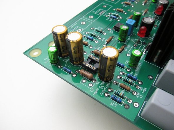
Opamp alignment - The dot on the body of the opamp is placed on the same side as the notch in the drawing on the silkscreen. The dot should be closer to the pair of 220uF capacitors.
-
-
-
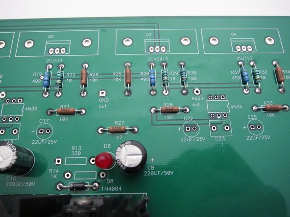
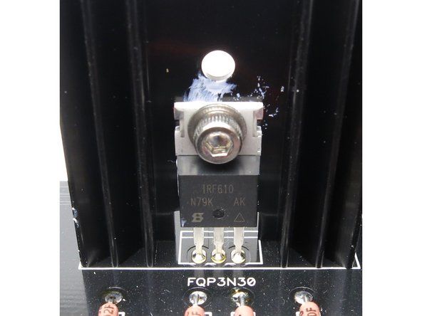
There is some ambiguity for in the markings of the output Mosfets in the schematic, the PCB silk, and the supplied devices. There are a number of devices suitable for these positions, with no significant change in performance.
-
Q1 and Q3 are the N-channel devices. The black PCB are marked "FQP3N30". Install IRF610, FQP3N30, or 2SK2013 in these positions.
-
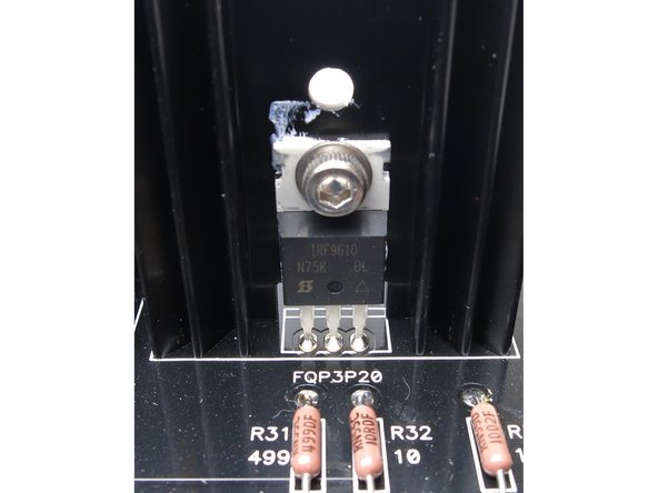
Q2 and Q4 are the P-channel devices. The black PCB are marked "FQP3P20". Install IRF9610, FQP3P20, or 2SJ313 in these positions.
-
-
-
The heatsinks are not attached electrically to the PCB, you do not need to use insulators if your TO-220 devices have metal tabs. A bit of thermal grease is extremely helpful. Align the device to he heatsink and snug on the screw, but do not make it tight yet.
-
-
-
Align all the pins and tabs before soldering. The heatsinks solder in. Then solder the pins. Now tighten the screws. (Not too tight! You can distort the device or break it.)
-
-
-
I used shielded mic cable in this build. Other wire will work, use what you have on hand.
-
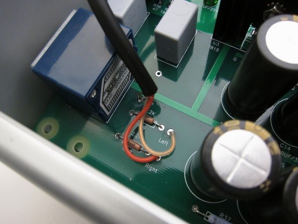
First image: Input at RCA jacks. The capacitor is a 0.1uF film cap of 50v or better rating. connect from the ground tabs of the RCA jacks to the safety earth at the chassis.
-
Second image: Input at PCB. In this photo the ground wire is mostly hidden by the jacketed cable.
-
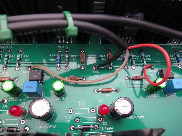
Third image: Output at PCB
-
-
-
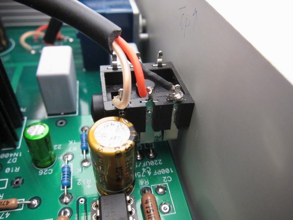
Output at headphone jack
-
-
-
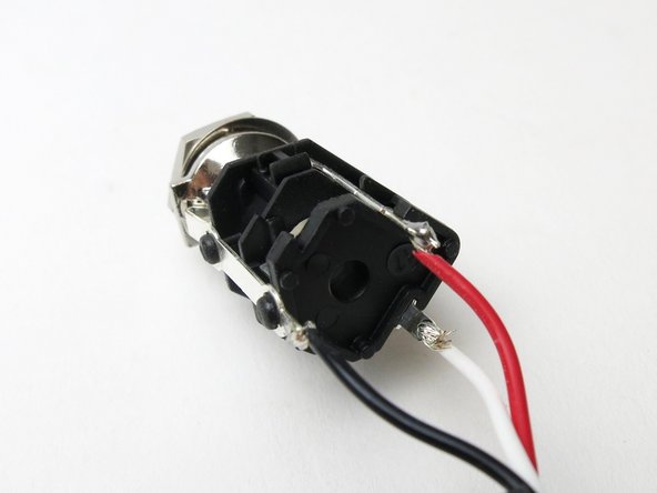
Photos of the headphone jack included in the parts kit.
-
-
-
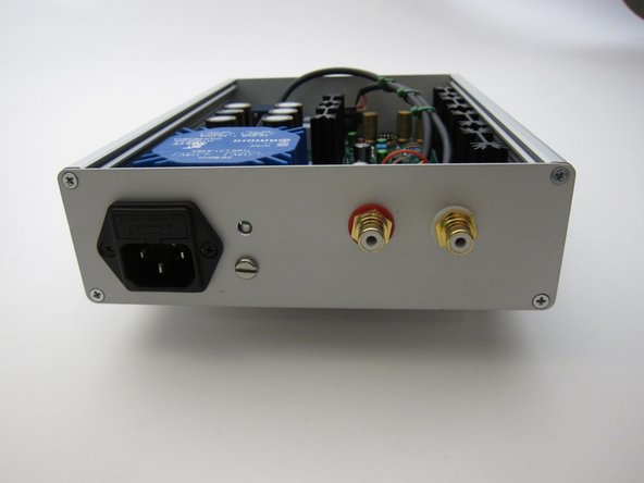
You can see that the whammy is snug in the Hammond enclosure. The inputs and outputs can be anywhere (or of any type) you wish to place the connectors.
-
-
-
Second image: Use this photo as an example of what NOT to do -- please move the IEC inlet to the middle of the back panel to get it away from the transformer.
-
-
-
Ripple after 1st caps
-
Ripple after 2nd caps
-
Ripple after 3rd caps, before the regulators. The lesson here? The “big and simple” approach of noise filtering using multiple CRC is extremely effective.
-
-
-
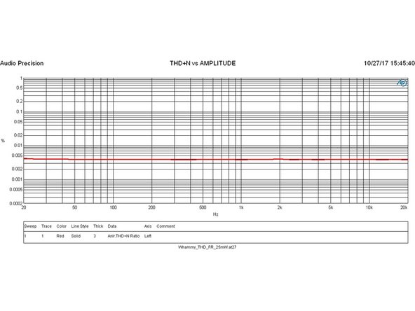
THD + noise vs. frequency
-
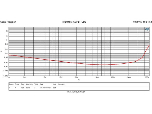
THD + noise vs. power output
-
Distortion residual from AP, this is mainly 2nd harmonic, and overall very low.
-
-
-
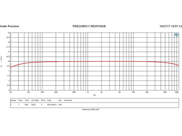
Frequency response
-
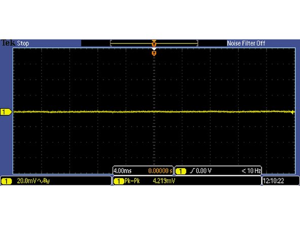
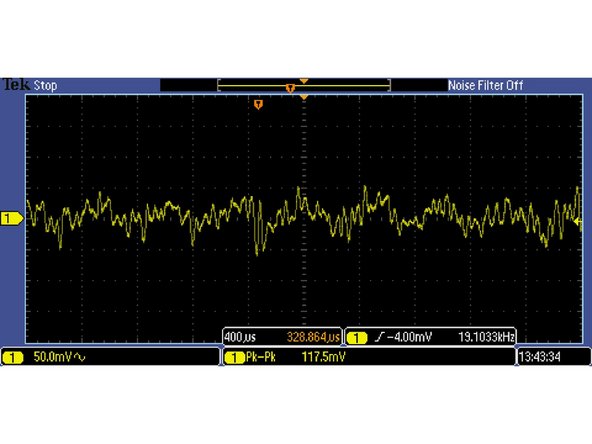
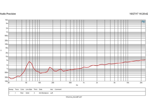
Noise floor
-
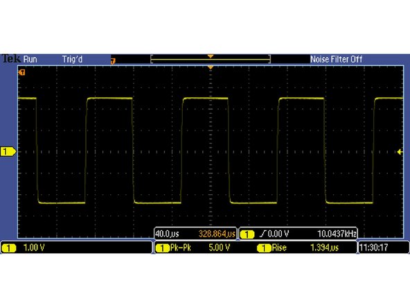
Square wave response. Clean, no ringing, very, very small shoulder at the leading edge.
-
-
-
Discuss your build, upload photos, ask for help and anything else in the WHAMMY build guide thread'' on diyAudio
-


We hope you enjoyed the guide! Please discuss your build, ask for help, upload photos and generally join in the diyAudio community discussion threads listed above!
We hope you enjoyed the guide! Please discuss your build, ask for help, upload photos and generally join in the diyAudio community discussion threads listed above!
Cancel: I did not complete this guide.
16 other people completed this guide.