
-
-
This guide will show the assembly of the Pass analog signal processor (ASP) for the Linkwitz Labs LXmini speakers.
-
-
-
Download and print (and read :) ) this .pdf -- http://www.firstwatt.com/pdf/art_lxmini%...
-
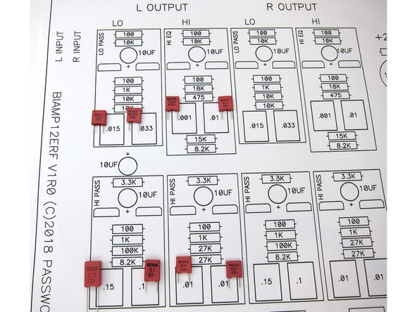
Print the three images here - Image 1) stuffing guide
-
Image 2) circuit schematic
-
Image 3) PSU schematic. Note that C28 may be supplied as 16V 3300uF or 25v 1000uf. If 3300uF is in your kit, only use in the C28 position
-
-
-
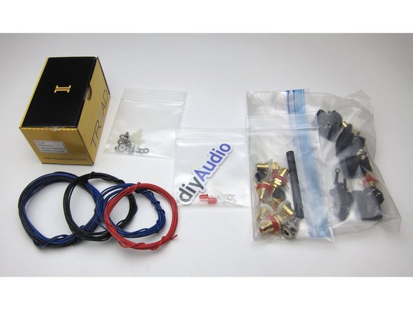
Parts kit includes 24v power adaptor, wire, LEDs (red and blue), standoffs, RCAs and XLRs, wire, and more.
-
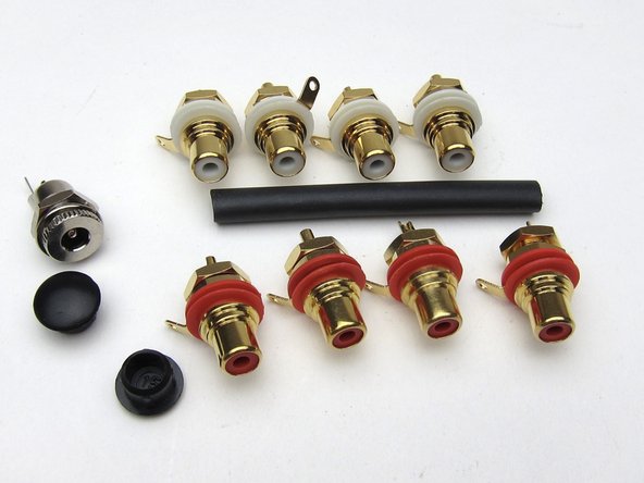
8 RCAs included (it will be the same parts kit for the 3-way version), heatshrink, hole plugs.
-
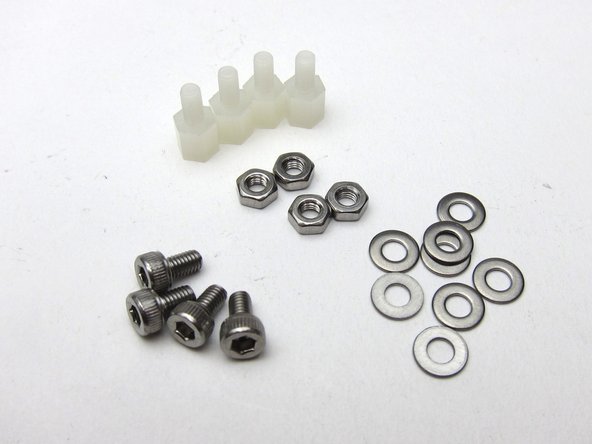
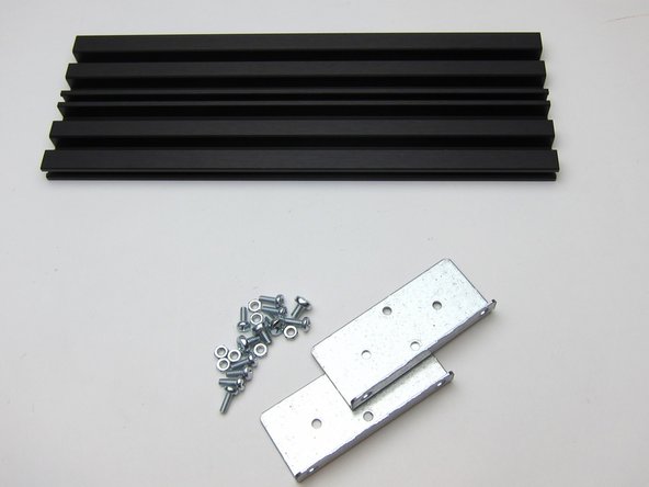
Standoffs and hardware.
-
-
-
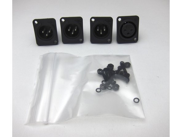
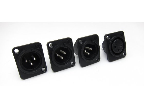
If you are wiring for balanced operation You'll use the XLRs, and need 2 crossovers as one PCB is required per channel.
-
As with the RCAs, enough are provided for the 3-way version
-
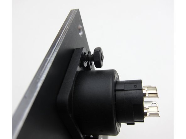
XLRs attach to the chassis as shown.
-
-
-
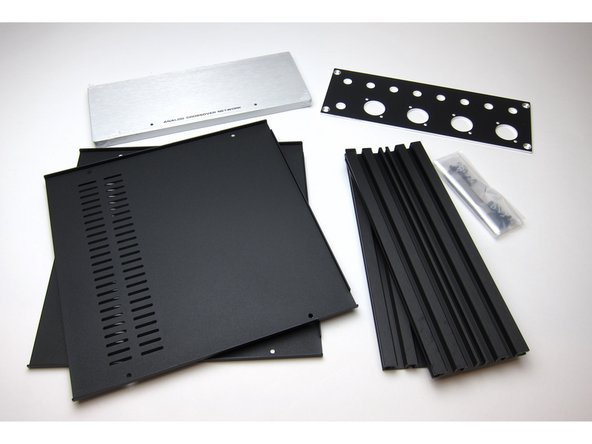
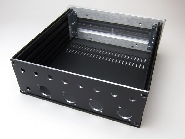
Chassis assembly is very straightforward.
-
Back panel attaches with screws into the extrusions.
-
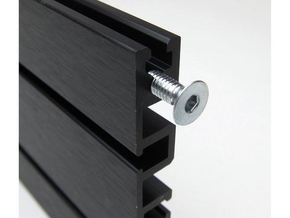
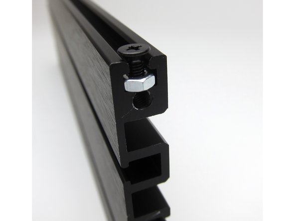
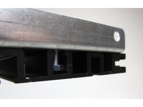
Top and bottom panels attach with screws and nuts in the rails as shown.
-
-
-
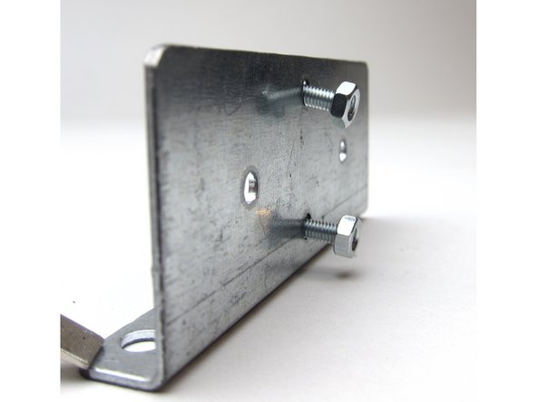
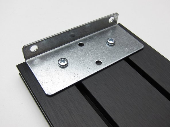
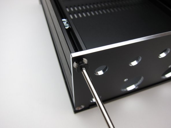
Attaching the thick front panel requires the 90deg brackets.
-
The hardware is attached to the bracket
-
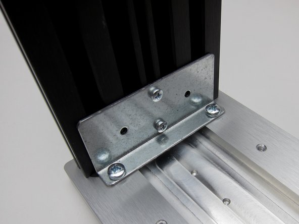
And it connects to the extrusion as shown.
-
If you want to have the other side of the extrusion visible, there are holes in the bracket to accommodate that. It's an aesthetic choice, with no functional difference.
-
See next step
-
-
-
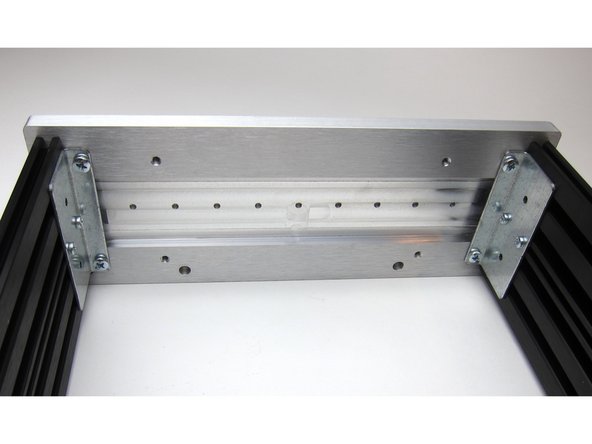
The tabs should be attached as shown.
-
Then bolt to the front panel.
-
Completed front.
-
-
-
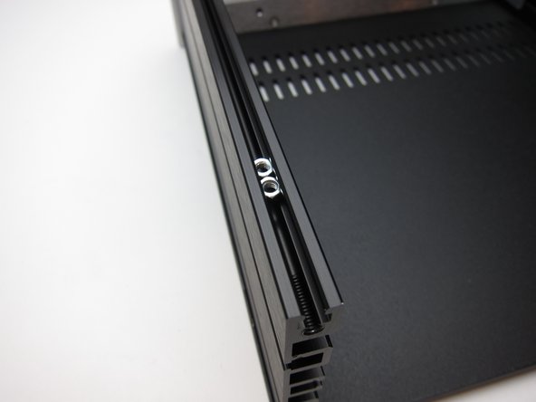
Insert the nuts in to the extrusion before attaching the back panel.
-
-
-
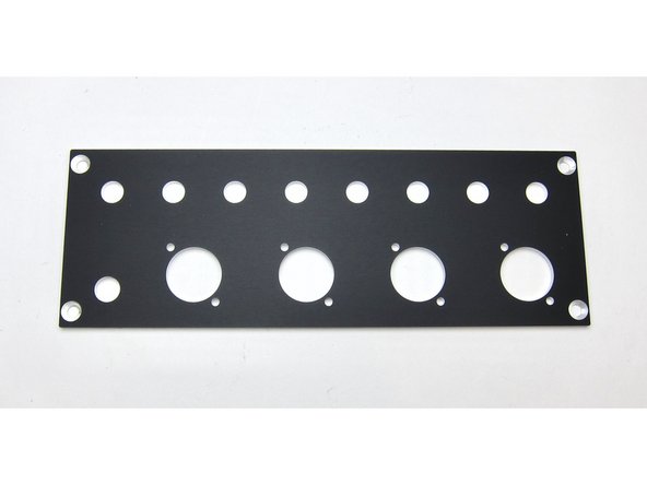
The front panel has holes for the LEDs
-
And the inside has an area milled out and starter holes if you want to attach any front-panel mounted potentiometers or switches.
-
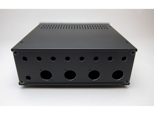
This is a prototype rear panel, the production versions will be labeled.
-
-
-
Completed chassis
-
Feet stick on the bottom. (Not shown)
-
-
-
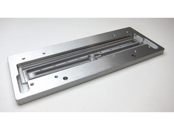
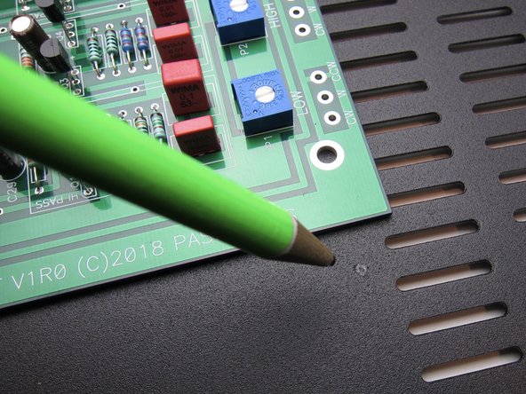
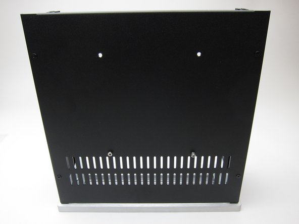
Use the PCB as a guide for drilling holes into the baseplate.
-
Mark the holes with a pencil and drill holes big enough for the M2.5 hardware
-
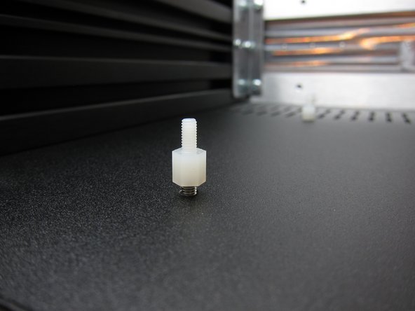
Attach standoffs
-
-
-
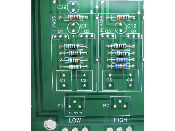
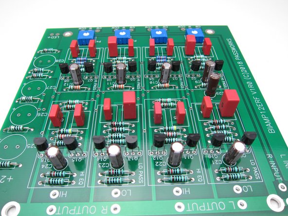
Photo 1) resistors nearest the output edge.
-
Photo 2) resistors nearest the potentiometers.
-
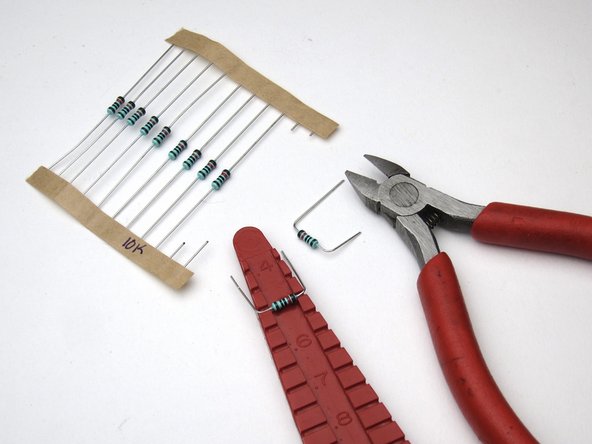
All resistors are on 0.5" lead spacing.
-
-
-
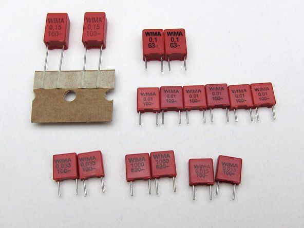
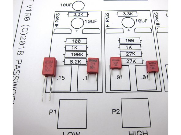
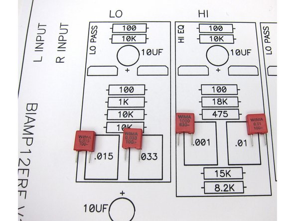
Signal capacitors are polypropylene. Note that the values are printed on the side in uF, but the smallest is marked 1000pF, which is equal to 0.001uF
-
Capacitor locations
-
-
-
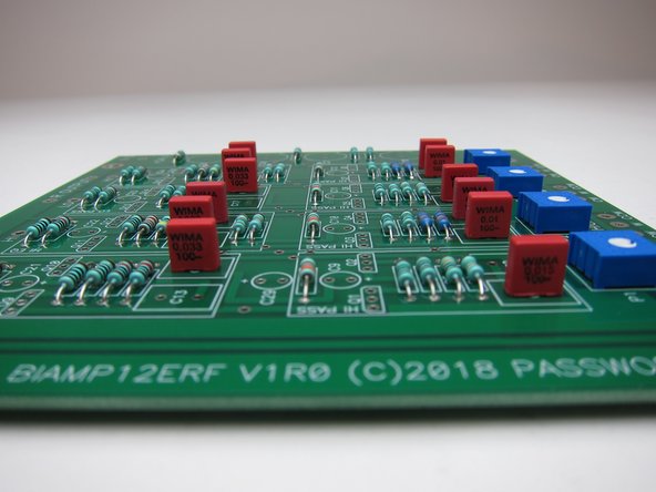
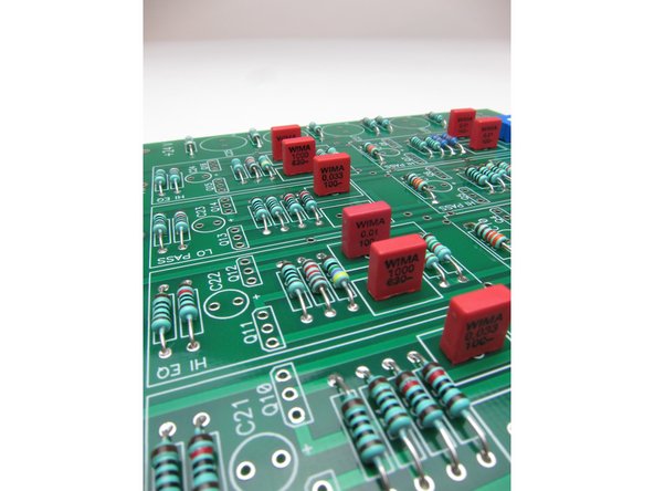
Closer photos of the capacitor locations.
-
-
-
Once the resistors, pots and xover caps are installed, next install all the transistors, small can caps, and large can caps.
-
Transistors all line up the same way, with the flat of the package in alingment with the flat of the silkscreen. Any supplied transistor in the kit can go anywhere on the PCB, they are all matched per kit.
-
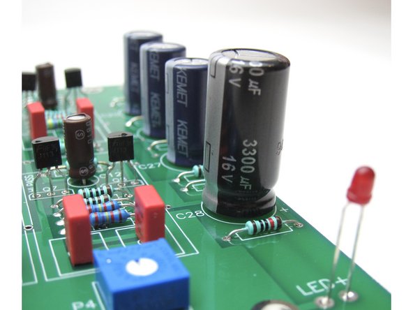
The small brown Silmic couling caps are next, do pay attention to polarity, one of them (C29) is backwards compared to the rest.
-
The PSU filter caps are last. If your kit includes the 3300uF capacitor, use only in the location shown.
-
LED shown for illustration
-
-
-
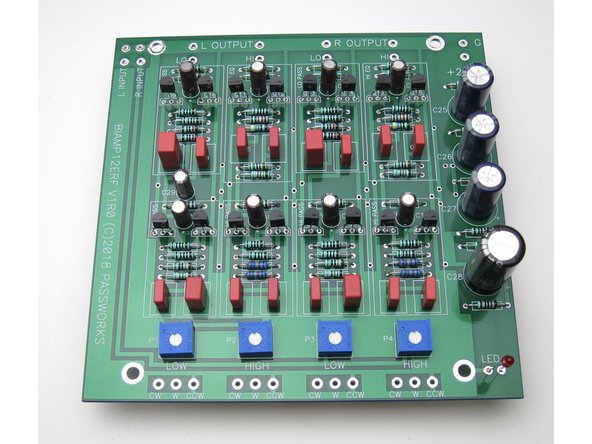
Stuffed PCB should look like this.
-
-
-
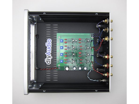
Attach PCB to chassis
-
-
-
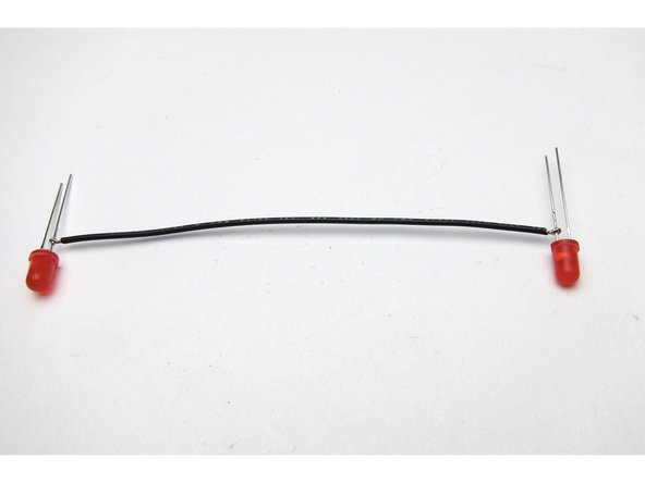
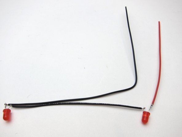
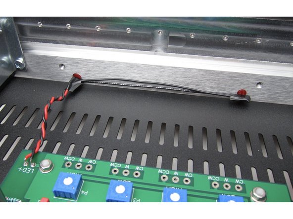
There are 2 LED holes in the chassis, so the LEDs need to be wired together. I choose series to make the light output dimmer.
-
Photo 3) Trim, insulate and twist.
-
-
-
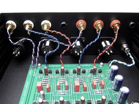
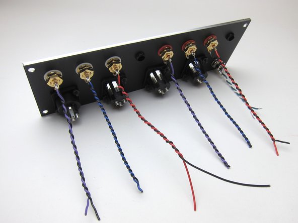
For the sake of clarity I used wire colors that may not be in the kit.
-
Purple /Black is Input
-
Blue/Black is LOW out
-
Red/Black is HI out
-
Green/White is power
-
XLR wiring will be shown in a future section.
-
-
-
Potentiometers are provided to adjusting output to match your amplifiers.
-
Adjust with screwdriver as shown. Turn all pots "all the way up" as a starting value.
-
Optionally, you may get chassis mount 25k potentiometers and connect them to the front and use the extra pads provided. If you choose to do this, leave the PCB mount pots unpopulated.
-
-
-
The back panel was populated with 6 RCAs, the 2 supplied plugs in the other RCA holes, the barrel connector for power, and the XLR connectors were used to close those holes.
-
I wired the RCAs and Barrel connector first. It may be easier to wire the PCB first and solder to the jacks in place. YMMV
-
-
-
This document has testing information, see page 11 and 12 -- http://www.firstwatt.com/pdf/art_lxmini%...
-
There is a turn-on and turn-off thump, the circuit is very low current and designed to run continually.
-


Cancel: I did not complete this guide.
14 other people completed this guide.