
-
-
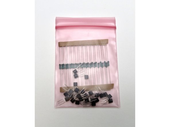
The bag of transistors is sorted before packaging, so that the transistors work in any spot if the included resistors are stuffed in the spots marked 'bias'.
-
-
-
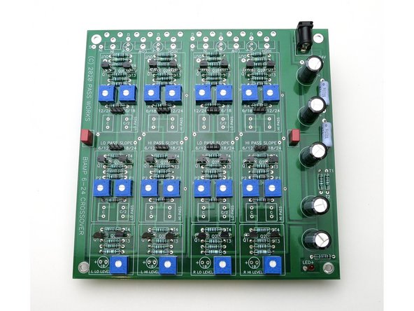
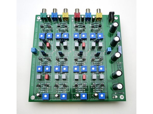
It's always a good idea in every project to stuff and test the PSU first.
-
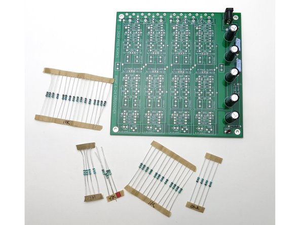
Photo 2 - Please gather these parts as shown on this portion of the schematic.
-
Feel free to swap the red LED for another color and/or change the brightness by adjusting the resistor as you like.
-
-
-
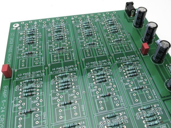
The film caps on the edges, the red ones in the photo, are actually part of of the power supply and are merely film bypass caps.
-
You can choose to leave them empty if you wish, or stuff with whatever value film capacitor you have left over, the specific value is not critical at all.
-
-
-
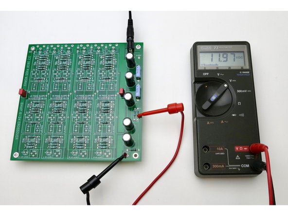
Let's do a quick check of the PSU before we go any further. You don't need to stuff the signal resistors for the step, I got a little ahead of myself in the assembly vs. the photos... :)
-
Connect power and connect your DMM as shown (the black is on ground, which happens to be the left leg of the LED, but anywhere on the PCB marked ground will be fine) and the red is at the V+ near the power jack. This should read the voltage of the PSU, which is 24VDC plus or minus a little.
-
Photo 2 - Now move the red probe to the leg of the small resistor marked "T2" and the DMM should read about half of the PSU voltage.
-
If you have both these voltages and the LED lights, wonderful! Please proceed.
-
-
-
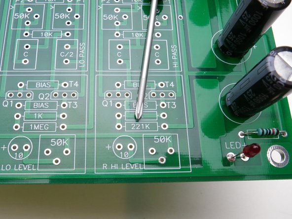
Photo 2 - please note there is an error on the silkscreen, in the single location where it says "221K", the marking should read "1 MEG"
-
The pink bag with the Jfets includes resistors for those specific transistors - they are all matched to one another. Use these resistors in the pads marked "bias".
-
Other than that, the PCB is marked clearly with the value of the resistors. Measure resistors before inserting and solder.
-
-
-
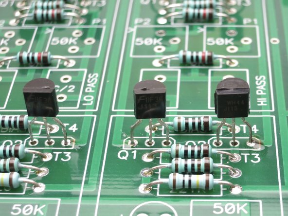
I like to insert the transistors and solder one leg from the top, this way you can get them mostly aligned, and then solder the rest of the leads from the bottom.
-
There are 72 Jfet legs to solder. Take your time. Neatness and thoroughness counts.
-
-
-
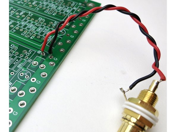
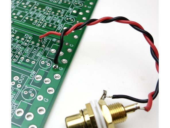
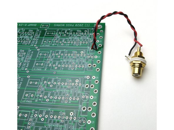
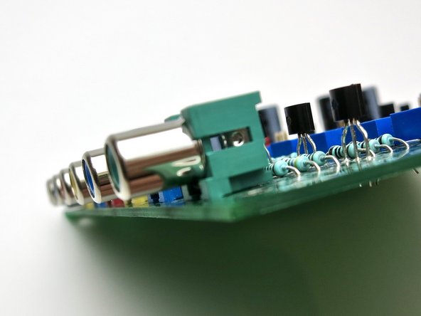
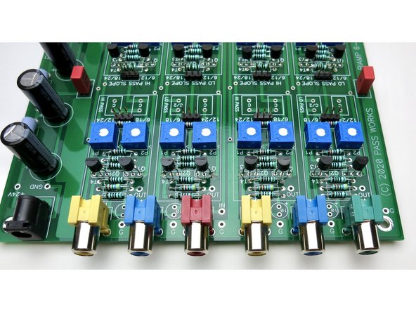
If you choose to wire this into a chassis with panel-mounted RCA jacks, they will connect as shown;
-
Photo 1 - The input is close to the ground.
-
Photo 2 - The output is a little bit of a stretch from ground.
-
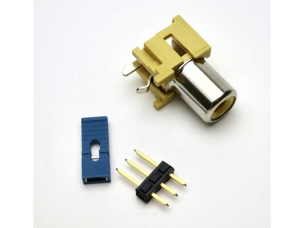
Photo 3 - Of course, you could use the solder pads from the PC mount jacks if you choose.
-
-
-
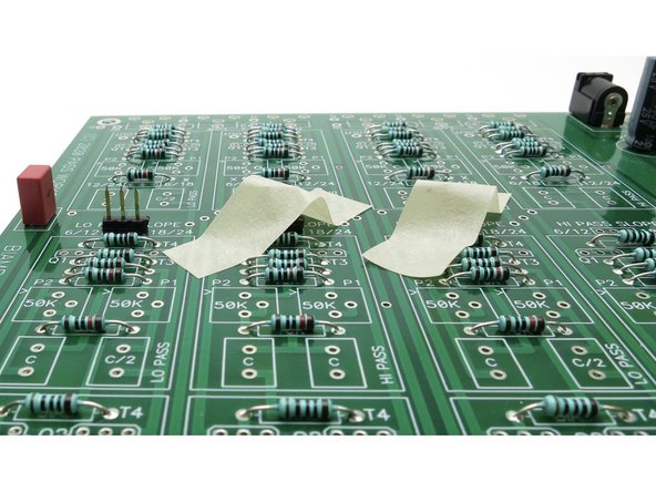
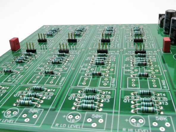
The 3-pin jumper switches will be installed next.
-
Photo 2 - The will fall out of the PCB if you don't secure them in somehow, it's easiest to use a little tape as shown.
-
-
-
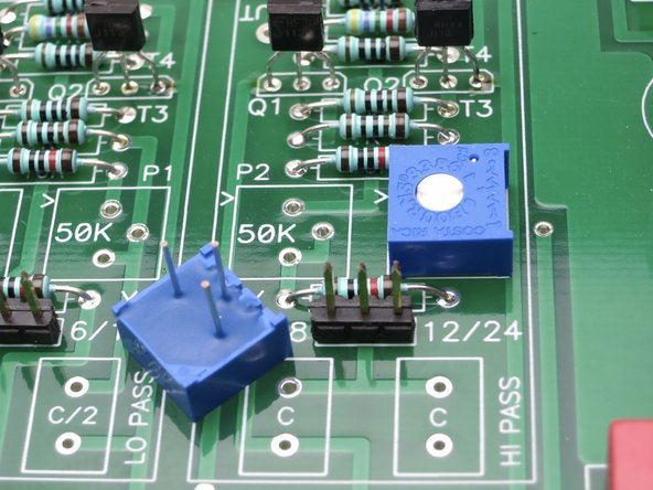
There are 20 potentiometers in this project, take your time and try to get them all lined up.
-
I like to bend the leads to hold them I'm place while looking/holding it from the top, this is the first step in alingment
-
Then solder the center leg of the pot only, flip back over, make a little adjustment to get it all squared up and in the lines as best as possible, and solder the remaining legs.
-
Neatness counts in this step. Take your time and try to get everything lined up nicely.
-
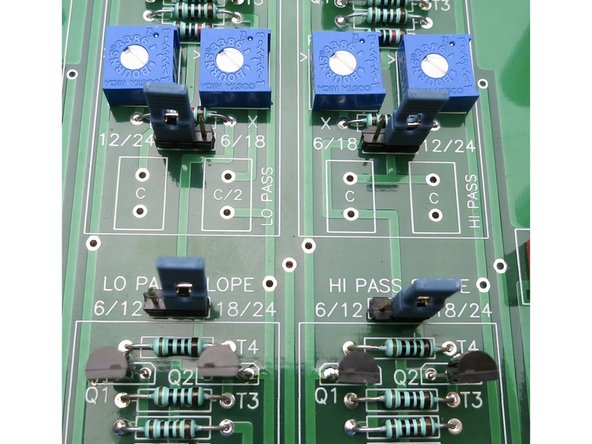
Photo 1 - note the little arrow > on the PCB, it is used to mark the middle point of the potentiometer range, and therefore the crossover frequency.
-
-
-
Please make sure you get the jacks mounted flat on the board before soldering.
-
You are welcome to use whatever color coding you like, the jacks are available in many colors. Search CUI Devices RCJ-041, there are colors from -041 through -047
-
-
-
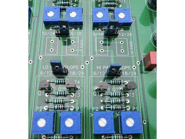
The jumper positions are labeled clearly, simply select every jumper to the desired filter slope.
-
Photo 1 - 6db/octave
-
Photo 2 - 12db/octave
-
-
-
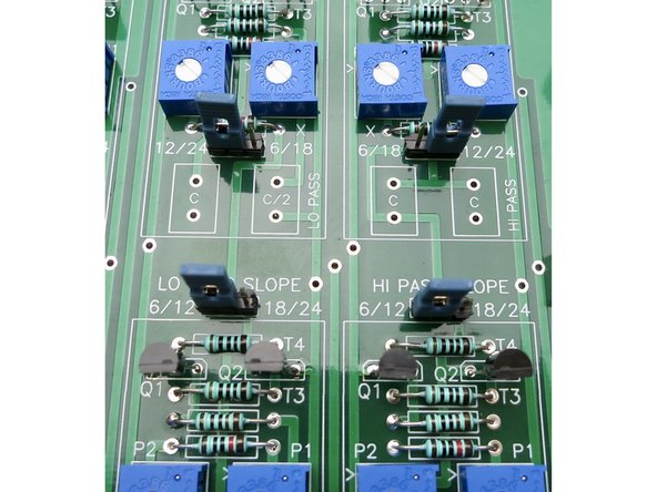
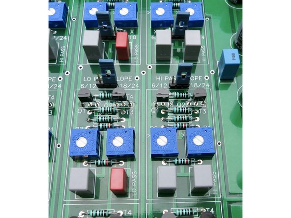
Photo 1 - 18db/octave
-
Photo 2 - 24db/octave
-
-
-
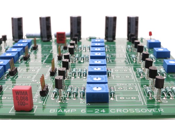
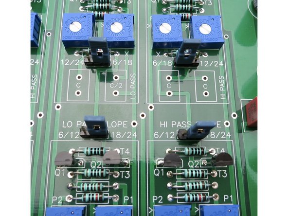
There are two values of filter capacitors, marked "C" and "C/2" on the pcb.
-
In these photos the "C" values are gray, the "C/2" values are red.
-
Note, the PSU film bypass caps have been changed to blue to reduce confusion in the photographs.
-
In total you will need (12) C and (4) C/2.
-


Cancel: I did not complete this guide.
11 other people completed this guide.