Introduction
This is a group of photos overviewing the basic steps necessary to build a DIY Firstwatt / Nelson Pass F5 Class-A amplifier. This build utilizes the v3 circuit board and the kit of circuit board parts available from diyAudioStore.com
-
-
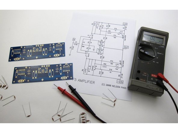
Print this out and have in front of you at all times.
-
Image 1) This is the schematic for the amplifier section.
-
Image 2) Schematic for the PSU section.
-
-
-
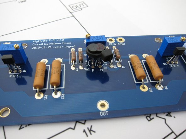
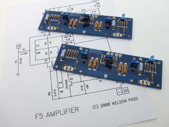
Photo 1) The current F5 PCB from the diyAudio store. It has the inclusion of potentiometer P3, and is the third revision of this board, hence "F5v3"
-
Photo 2) Right - PCB bag. Left - Kit of F5 parts.
-
Photo 3) The parts kit includes everting for the amp PCBs except the input Jfets and the LED
-
-
-
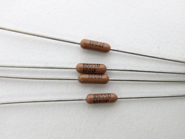
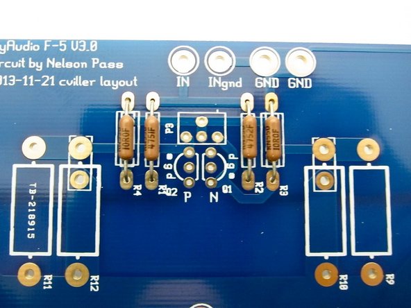
The Dale resistors have thier value printed on the side, the code is 3-digit + multiplier at values greater than 100ohm, and below 100ohm the "R" is the decimal. So, from top to bottom you see 10K (100+2 zeros, 10000ohm) 1K (100+1 zero, 1000ohm) 100 ohm (100+0 zeros, 100ohm) 10.0 ohm (10R0, 10.0 ohm)
-
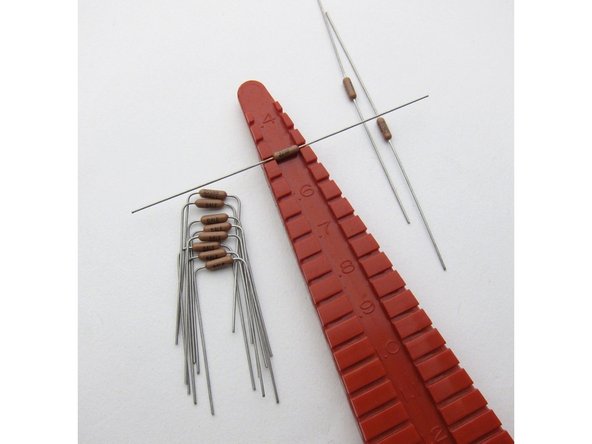
Lead spacing for all small resistors is .5inch (12.7mm)
-
Measure all resistors before inserting into the board. This greatly reduces errors.
-
-
-
Take the time to bend all the leads so the value is visible, and align them all the same way for easy reading.
-
Photo 1) left side
-
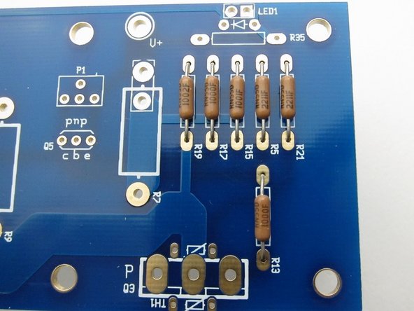
Photo 2) center
-
Photo 3) right side
-
-
-
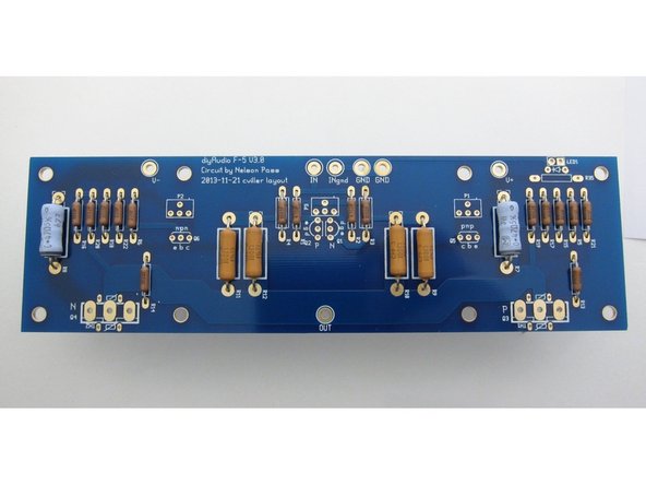
Big resistors installed. Blue are 0.47ohm 3W, Orange are 100ohm 3W. Values printed clearly on the side of each resistor.
-
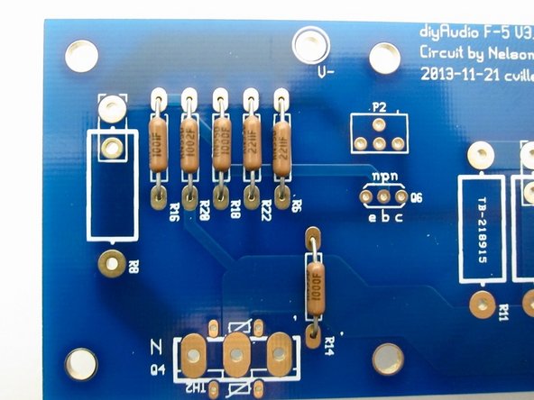
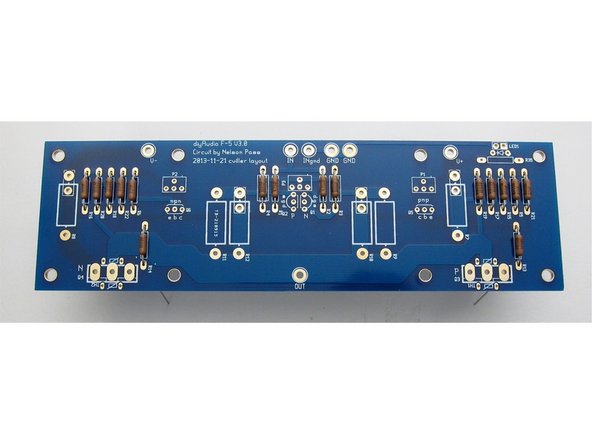
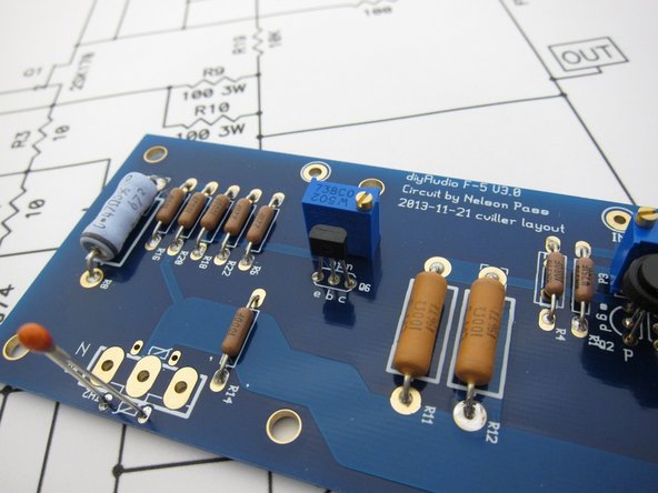
Photo 2) PCB with just small resistors.
-
-
-
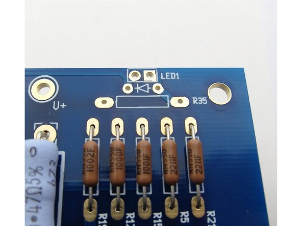
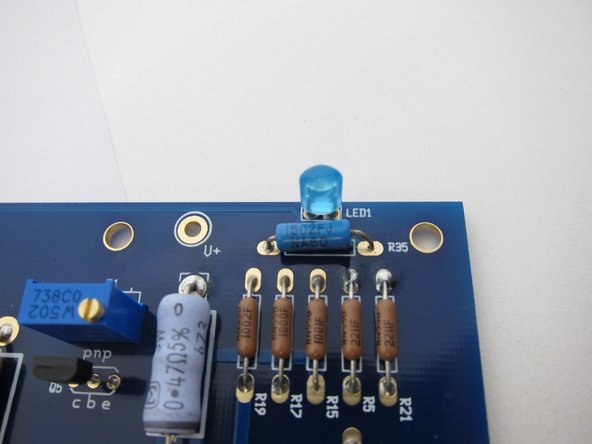
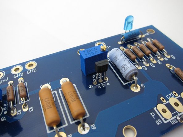
Note that the parts kit does not include the LED or it's resistor, this is so you can choose that you prefer.
-
I used blue and a 15K resistor
-
-
-
Install the 5K pot and the ZTX450 on this side (Q6). Note the orientation of the transistor. The potentiometer value is almost the same code as the resistors - 502 is 50+2 zeros , 5000 ohms
-
Q5 is the ZTX550, note orientation, and use another 5K pot here.
-
The 200ohm pot mounts in the center, and the Jfets install as shown. The K170 is the N-channel, the J74 is the P-channel.
-
-
-
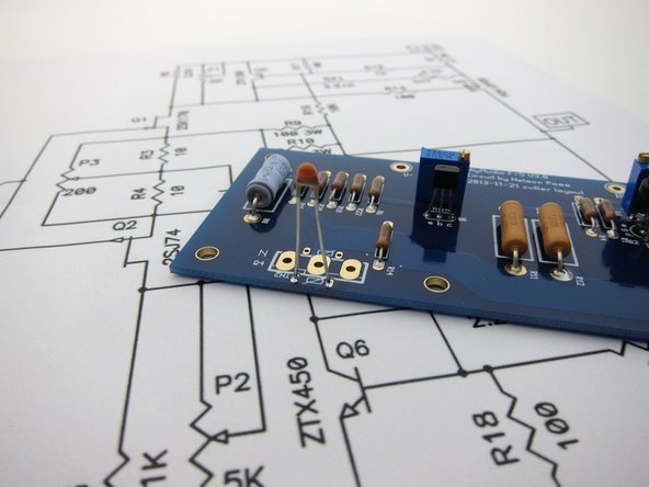
Mount the thermistors as shown and don't bend then yet.
-
-
-
At this point the amplifier PCBs should look like this - all components stuffed except power transistors, and the thermistors not bent.
-
-
-
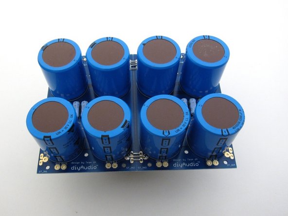
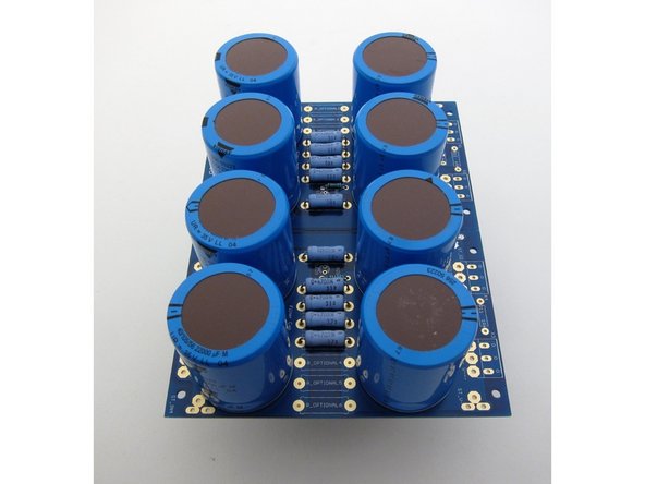
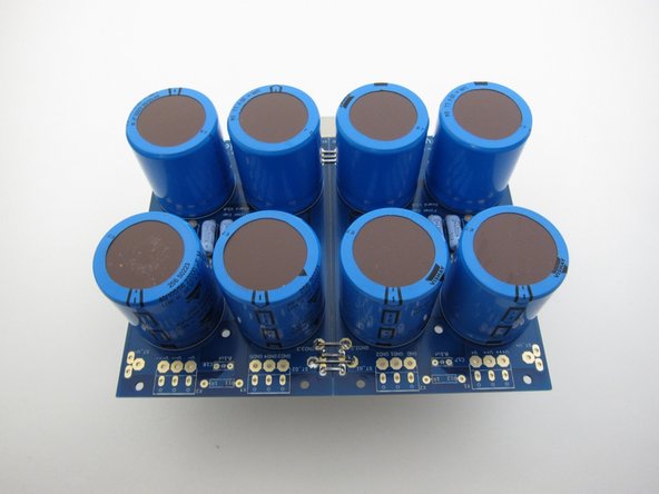
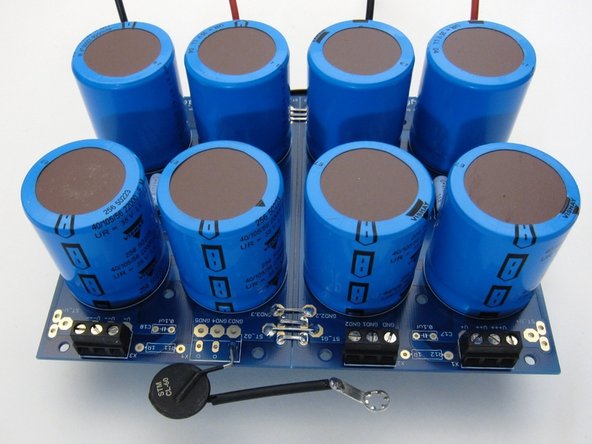
This is the PSU board from the store, the diode section is snapped off and chassis mount diode bridges will be used to save space.
-
Photo 1) input side
-
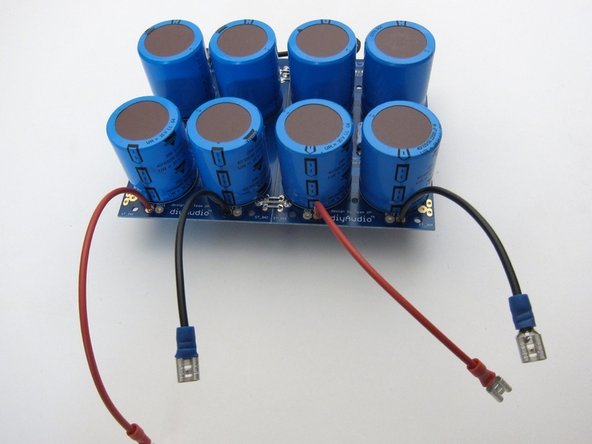
Photo 2) center
-
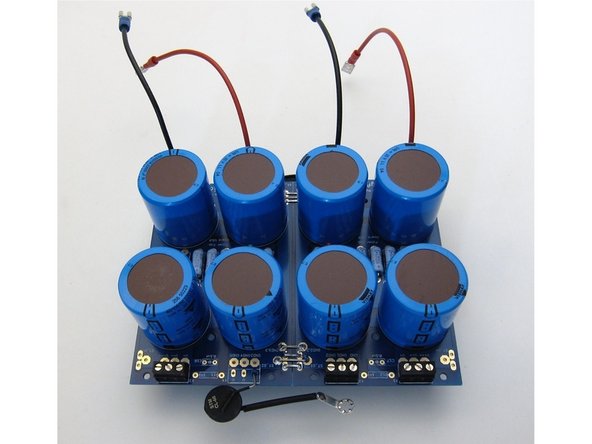
Photo 3) output side
-
-
-
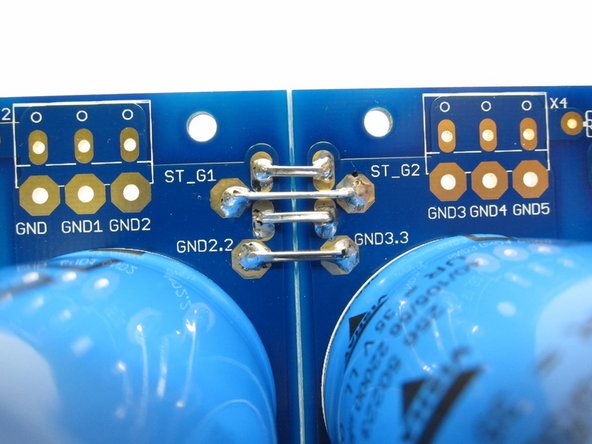
Photo 1) Please connect the two sides of the ground as shown - it won't work properly without it. Use a few wires or lead cut-offs, to insure a solid, quiet, and low-impedance ground.
-
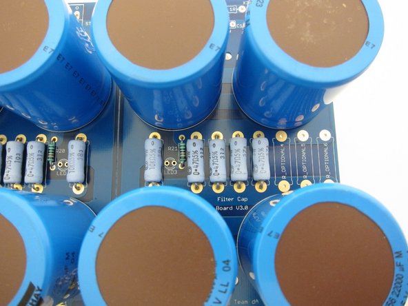
Photo 2) Filter resistors, bleeder resistor, LED resistor. LED not stuffed, choose whichever color you like, you could color code V+ and V-, or make them bright blue to fill the vent holes with color, it's up to you.
-
You can stuff both connector blocks on ground, but if you use one, you will have all the grounds closer to the same place, acting somewhat as a 'star ground'.
-
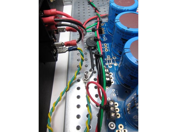
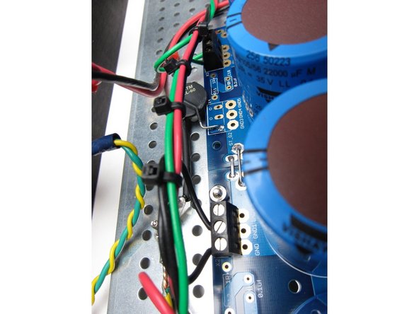
The CL-60 is acting as a ground loop breaker, elevating the amplifier circuit with a resistance above mains earth, but can flow current if there's a fault.
-
-
-
PSU ready for installation. Blocks installed, wires to connect to diodes ready, thermistor with star washer.
-
-
-
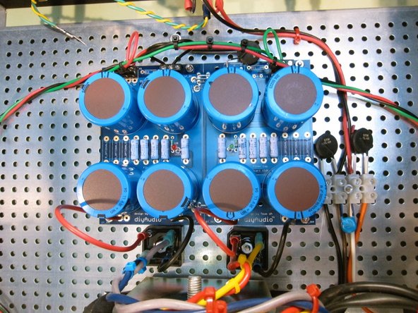
Diode bridges to PSU board.
-
-
-
Safety earth (Green Yellow) is connected from the power switch module to the chassis. Use a star washer to ensure a solid connection.
-
-
-
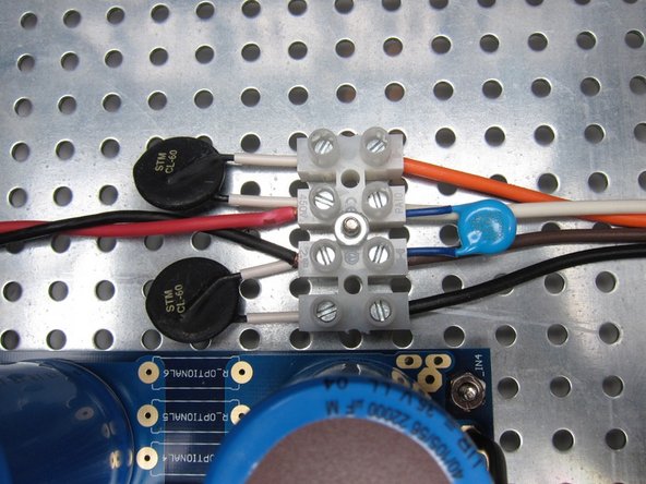
Terminal block. 120VAC wiring shown. AC from switch in from left (Red Black) CL-60's, the blue disc is the X1/Y1 rated capacitor, and transformer primaries are out the right.
-
-
-
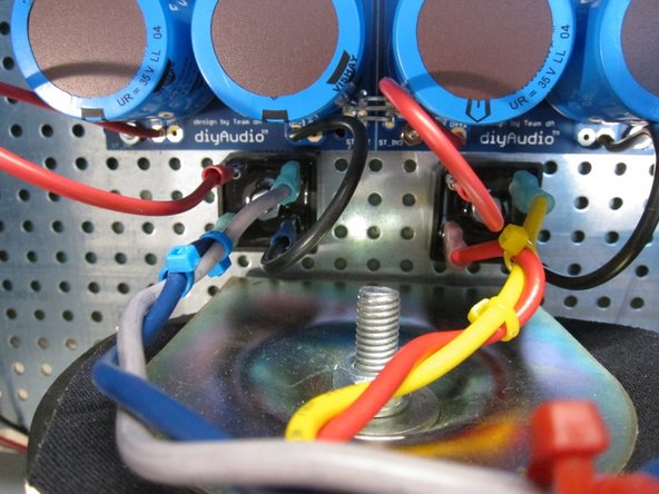
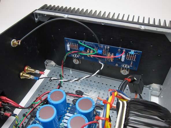
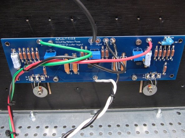
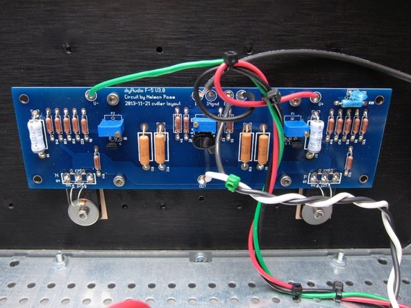
Connections from amp PCB to back panel.
-
Try to arrange the wires so they are not in the way of the potentiometers. Zip-ties are your friend!
-
Note the small thermistors are bent down now and touch the washers holding the Mosfets.
-
-
-
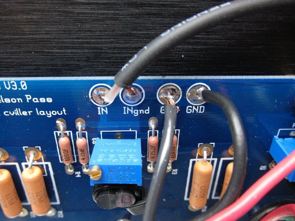
The PCB connections to GND are all tied together, but it's still nice to have individual holes for the wires. Input ground from the RCA jack, speaker, PSU.
-
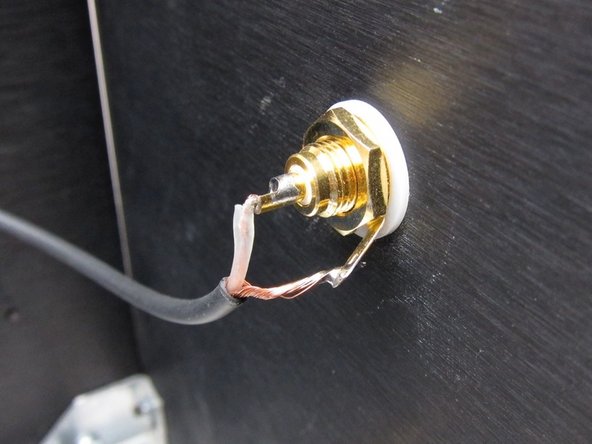
Photo 2) RCA wiring
-
-
-
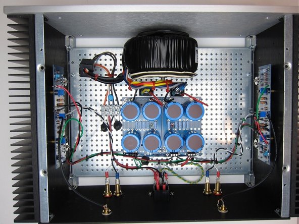
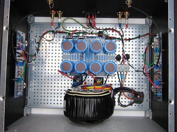
Photo of completed amp.
-
Cancel: I did not complete this guide.
40 other people completed this guide.


