Introduction
What Are We Building?
This guide covers the assembly of a stereo Babelfish F8 amplifier using the Simple Linear Bipolar Power Supply in a Deluxe 3U chassis.
|
What Is Covered In The Guide?
This is a build 'guide'. It is not an instruction manual. The purpose is to assist in learning and guide DIYers with helpful information. Builders should not expect every detail to be covered.
It is not the only information needed to complete the project. Some additional links are included as guidance. It is critical to understand that the guide is an EXAMPLE of how to complete the project. It is not the ONLY way to complete the project. DIY is all about choosing your own adventure. Have fun!
|
The project is considered moderately difficult. The guide is not intended to instruct someone that has never built an audio amplifier through their first project. This guide is best suited to someone with an interest in audio electronics that has built one or two audio projects, is ready to take the next step, or just needs a few helpful hints.
|
Builders should have a basic knowledge of electronics and should be proficient in through-hole PCB soldering. There are two SMD resistors, but they are large parts (relatively speaking) and the kit contains several extras. Although there are many helpful tips throughout the guide, before attempting to build this project, the builder should be confident in their ability to:
- SAFELY work with electronics powered with mains voltage,
- follow a schematic and identify the proper placement of parts from the schematic onto the PCB,
- understand basic measurements to identify parts correctly, and
- properly solder a variety of through-hole components.
|
What Else Is Required?
A list of major parts and critical tools used in the example have been provided. Not every part required for a build is included with the kits. Not every tool you may need for your personal build is noted. This is DIY; builders can and should improvise. Links are provided in the Tools & Parts section for examples of most of the tools and parts required to complete this project, but the options are limitless.
|
Most importantly, if you have questions, please seek help in the forum.
|
Enjoy!!!
Tools
-
-
A black bullet is explanatory or contains valuable information.
-
Everything in this guide is important, but here's how you'll know something is REALLY important.
-
A green bullet is the mark to do something.
-
A yellow bullet indicates a fun fact.
-
Warnings will be noted with a warning symbol and bold, red, underlined text. Pay Attention!
-
Tips and tricks and helpful reminders will be noted with an information bullet.
-
Photo / Image captions and information will be noted with the Photo/Image Icon.
-
-
-
Click on the image to enlarge and read the warnings carefully.
-
-
-
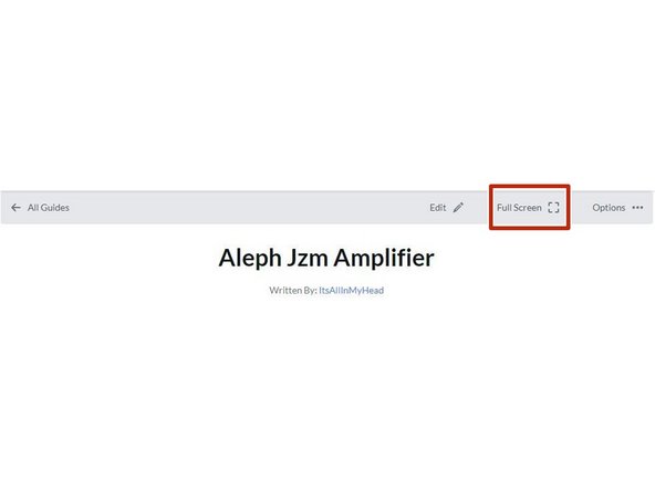
Your first "real" black bullet. You may notice that you have the option to view in "Full Screen". This web platform works well with tablets too. It has been tested it with various monitors of various aspect ratios and tablets. Choose what looks best to you. The printed .pdf format is nice too.
-
Image 1 - To switch to "Full screen", take note of the box around "Full screen" at the top of the guide above the header / title. That's where you click to move to Full Screen.
-
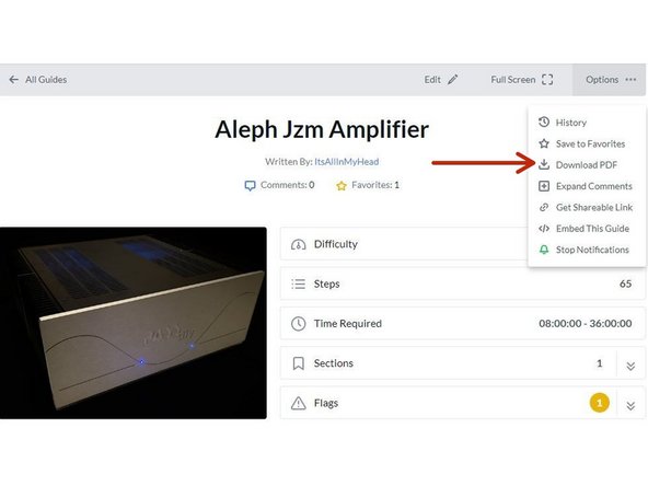
Image 2 - Note that you can download this guide as a .pdf and print it. Click the options button in the upper right.
-
In all the on-line views, if there are multiple images and/or photos within a step, mouse-over or tap/click as appropriate to make which ever one you'd like the primary image (the biggest one).
-
Mousing over / tapping on the primary image will change the cursor to a magnifying glass. Clicking / double tapping will open a new tab or enlarge and center the image on your screen.
-
In full-screen mode, the keyboard right and left arrows or clicking the arrows in the upper right of your screen will advance or reverse one step.
-
Your first "real" green bullet. Choose if you want to view in full screen or standard (if you haven't already) and/or print a copy of the guide.
-
Get started. Move on to step 4.
-
-
-
All mistakes are preventable, and this guide moves slowly through each step.
-
The most common issues with builds are mis-stuffed parts and poor solder joints.
-
Symptoms from mis-stuffed parts typically manifest quickly. For this build, pay particular attention to the small resistors and the TO-92 packaged transistors. The impact from an improper part placement can be benign, or you could release the "magic smoke".
-
The impact of poor soldering varies. A short/bridge that will impact your build is unlikely, but can be catastrophic. More commonly, the issues are partial coverage or a cold joint. Symptoms may not manifest until you least expect them, and they may be intermittent. Inspect each and every joint under magnification. You'll be glad you did.
-
DMM issues can lead to frustration.
-
Check the batteries. When in doubt, replace the batteries.
-
Make sure your probes are reading "0 Ohms" resistance probe to probe or are appropriately compensated.
-
Make sure your probes are connected properly and free of finger oils. A quick wipe with IPA will clean them nicely. For this guide, the polarity of the voltage being read isn't critical, but it's best practice to understand the polarity. As an example, if you are troubleshooting an issue, it is likely that the polarity will matter.
-
-
-
The notation of voltages requiring a decimal place will have a "V" in place of the decimal. 24V5 is 24.5 Volts or 24,5 Volts.
-
The notation of resistance requiring a decimal place will have a "R" in place of the decimal. 0R5 is 0.5 Ohms or 0,5 Ohms.
-
The notation of Amperage requiring a decimal place will have an "A" in place of the decimal. 1A1 is 1.1 or 1,1 Amperes.
-
-
-
The most common action you'll take throughout the guide is to "install" your parts AKA stuff the PCB. Parts installation includes:
-
Ensuring you have the correct parts to match the PCB silkscreen / schematic.
-
Ensuring the leads are clean / free from finger oils, and are bent to the proper pitch (if applicable).
-
Validating the orientation of the part (as applicable) and inserting the part into the boards along with ensuring any vertical spacing (as applicable).
-
Soldering the parts into place.
-
Cutting the leads to the proper length*
-
It is also acceptable to clip the leads to the correct length prior to soldering. There are compelling reasons to do it either way. If you are unsure, watch a few videos, read a few articles, and do some test soldering of your own to see what works best for you. If you choose to clip prior to soldering, use the correct tool.
-
Cleaning and inspecting the joint. It is strongly recommended to use magnification and good lighting to inspect each and every joint.
-
-
-
This guide does not cover how to solder / install through hole parts. There are a variety of great ways to install a part and achieve a proper solder joint, but there are common themes throughout. Below are a few links. See what works best for you. Neither diyAudio nor the author have any affiliation with any of the companies or persons linked.
-
-
-
-
-
Image 1 - A basic soldering sequence and examples of both good and poor joints. Taken from the Rayming PCB & Assembly Guide linked above.
-
The key variables to soldering are the type of solder chosen, the tip used, and the tip temperature. These all vary widely between users and are inter-related. If you are new to electronics, the best solution is practice. Scrap electronics and inexpensive parts are a wonderful way to learn.
-
Leaving the iron tip on the joint for longer than around 5 seconds is not a substitute for too small an iron tip or too low a temperature. If you need to reflow a joint, or if the solder isn't flowing, flux is your friend.
-
-
-
Plan your build. Read this guide a few times before you even take the first part out of the bag.
-
Go slowly. You're not getting paid to do 100 boards a day. This should be relaxing and fun. A lot of errors can be traced back to lack of attention and rushing.
-
The ONLY parts within reach should be for the step you are working on at the moment. Many parts look very similar.
-
Move the boards and your body around to give yourself the best angle to solder each part. Get close to your work and use magnification. A well-lit workspace is important. You don't stand a chance if you can't see.
-
Before moving to the next part, triple check your work. Hopefully you won't make any errors, but it is much easier to remove one part than many to fix an error. Using the included documents and following a basic sequence will assist with error-free construction.
-
Take plenty of breaks and stop at any point confusion or frustration sets in. There are a few recommended stopping points throughout the guide, but stop any time you mentally or physically need to recharge.
-
Try to keep distractions to a minimum.
-
Neatness counts!!! Take pride in your work. You'll be happy you did.
-
-
-
Print a copy of the schematic and two copies of the installation checklist found at the end of this guide or in the Documents Tab if you are viewing in Full-Screen Mode. You'll need to go back to the Introduction (full-screen mode) or scroll to the end of the guide to find the documents / documents tab.
-
If using a PC or similar, right-clicking on the "view" link will allow the document to be opened in a new tab if you'd like to keep the guide and the documents open at the same time.
-
Note - Schematics are not representative of the board layout. The schematic is not an overlay for the boards / traces / parts.
-
The installation checklist along with the schematic are exceptional tools for ensuring all parts are installed properly.
-
Tidy up your workspace. Keep in mind that you'll be working with a very hot soldering iron, and it can be easy to misplace parts. A few recommendations:
-
No other parts for any other projects should be within arm's reach.
-
The floor and the area around the workspace should be clean, just in case a part escapes. The kits contain small parts. It can be very frustrating to wait several days for a single part if you lose one. Extra SMD parts are provided with the kits, because it's almost inevitable that you will lose one (or more).
-
-
-
Find a clean, open space on your workbench and open the kit. The kit contains two PCBs and two bags of parts. It's a good practice to empty parts into a bowl or somewhere that parts cannot wander off the bench. Take care to not drop any parts.
-
Note - The part lot numbers and manufacturers will change over time.
-
-
-
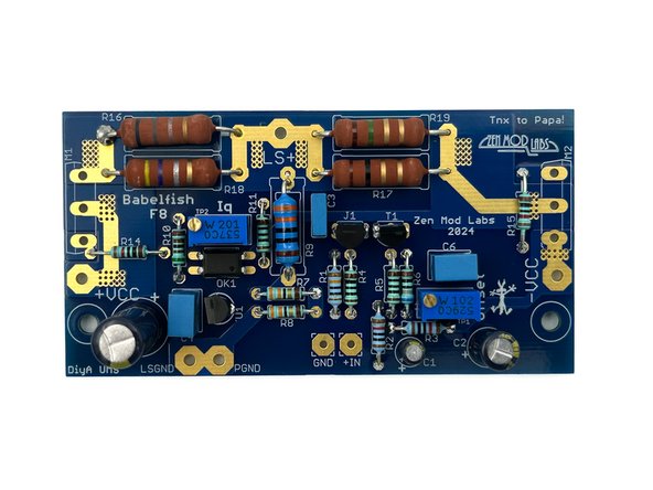
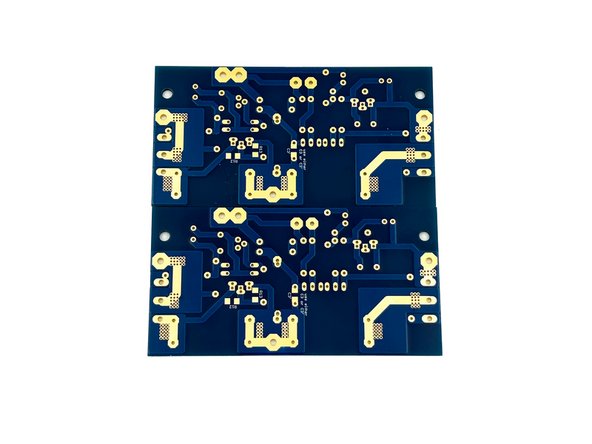
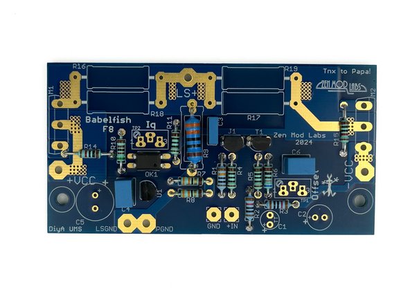
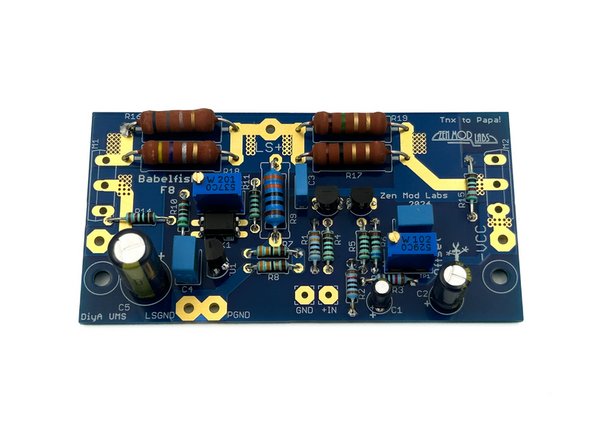
Look over your boards and get familiar with the parts placement. Check the board against the schematic. Both boards are identical.
-
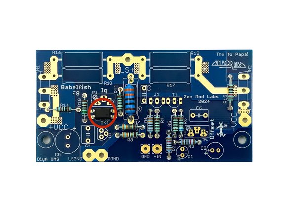
Image 1 - Front view of the PCBs.
-
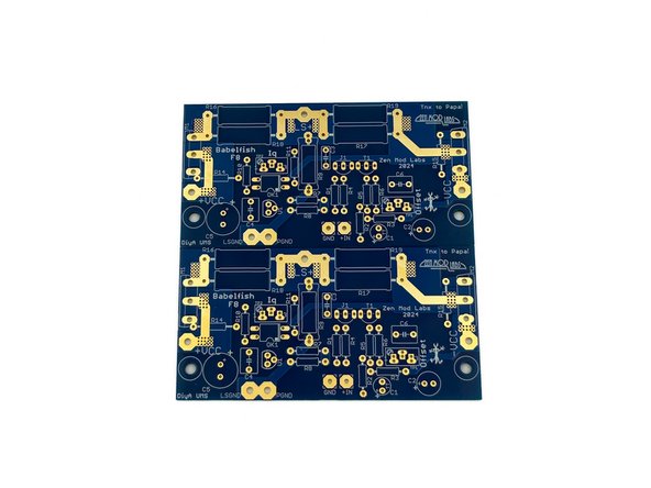
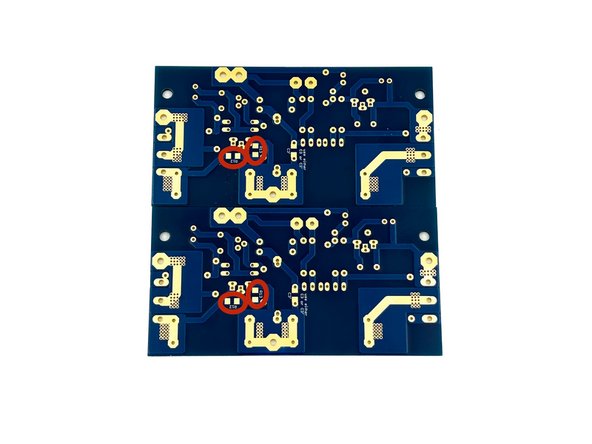
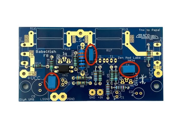
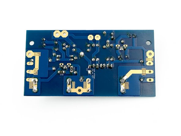
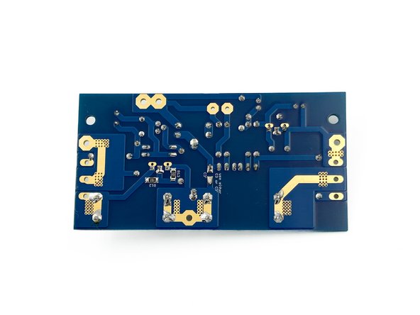
Image 2 - Back view of the PCBs, sometimes referred to as the solder side. You will install two SMD resistors on the back of the board.
-
Clean both sides of the board with isopropyl alcohol or your favorite PCB cleaner. A dust and oil free board helps the solder to flow nicely.
-
Ambitious DIYers may trace the board with a DMM in continuity mode against the schematic. It's not necessary, we've done it for you, but give it a try.
-
-
-
Installing the SMD resistors (R12 and R13) is not as challenging as many people think. Take your time. If you do not have a preferred SMD installation method, the steps that follow work perfectly for many people.
-
Magnification and good lighting are critical to success.
-
For these pads and resistors of this size, micro-sized iron tips and ultra-thin solder are not necessary. The video demonstrates using Cardas Quad Eutectic solder and a typical chisel tip used for through-hole soldering.
-
Be very careful when opening the strip of parts. It is recommended to carefully open one part at time over a mat or into a bowl.
-
Photo 1 - The parts go on the back of the boards
-
-
-
Wet one of the pads for each resistor with a small amount of solder.
-
Using tweezers, gently place the part next to the pad, maintaining control of the part. One common error is squeezing the tweezers too tightly. A very light pressure is all that is needed.
-
Heat the solder, and slide the part into the molten solder.
-
Ensure the part is placed to your satisfaction before moving forward. If the part needs a small adjustment, reheat the pad and adjust the part.
-
The parts do not need to be perfectly aligned.
-
Once the part is oriented to your satisfaction and covering both pads, solder the other side of the part to the open pad.
-
Touch up the original joints if necessary. If you've used a solder with a lower percentage of flux / rosin, adding liquid flux / rosin may be appropriate to ensure perfect joints.
-
Video 1 - Installation of R12 and R13
-
-
-
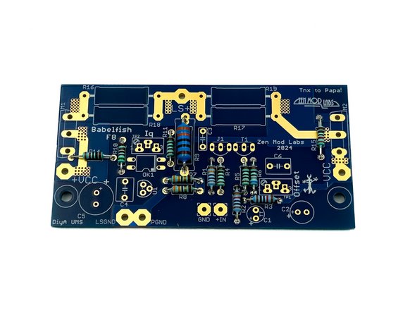
Remember to measure the resistance for every part before installation.
-
It is helpful to use a lead forming tool. The pitch for the small resistors is 10mm. The pitch for R9 is 15 or 18mm. Use either set of pads for R9.
-
Having all the resistors oriented the same way helps tremendously with troubleshooting. In this build, the bands will read from left to right or bottom to top. The thick brown band is "band 5" for these resistors.
-
Install all the small resistors along with R9. It's not strictly necessary, but leaving a small amount of space between R9 and the PCB is a good idea.
-
Photo 1 - The boards should look like this.
-
-
-
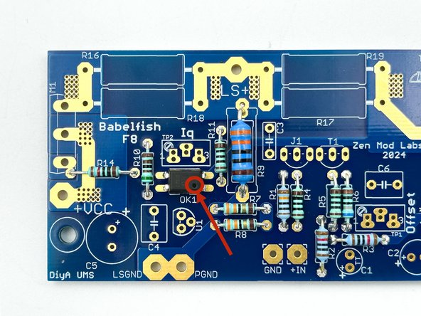
Ensure you pay attention to the small dot on the PCB and the optoisolator. They must be aligned.
-
Photo 1 - Notice the location of the dot (Pin 1).
-
Install OK1 on both boards.
-
Photo 2 - OK1 installed
-
-
-
There are two values of film capacitors. They should be very simple to sort by size and quantity.
-
Install C3, C4, and C6
-
Photo 1 - Film Caps Installed
-
-
-
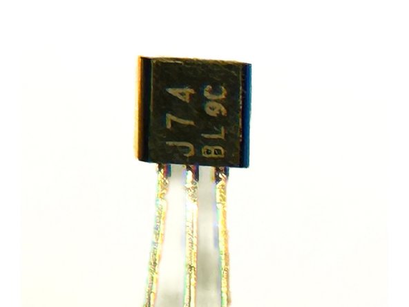
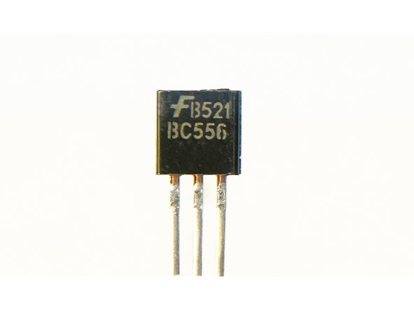
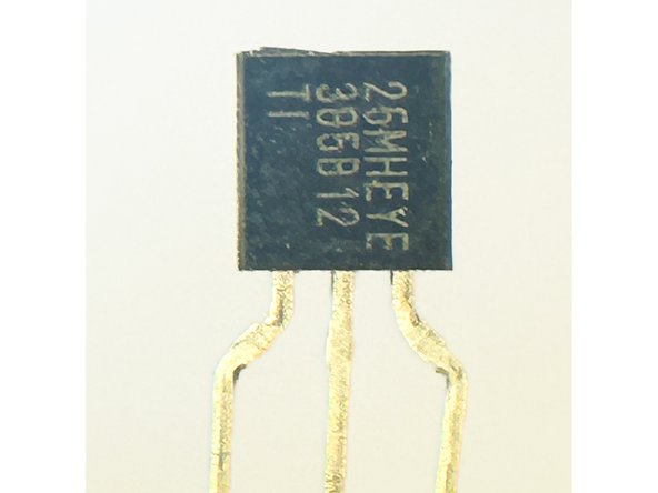
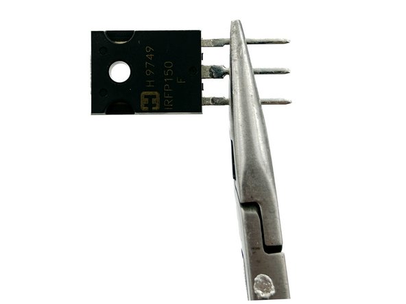
The kit comes with 3 types of transistors in a TO-92 package. It is critical to separate them and install them in the proper locations.
-
Using any appropriate magnification, separate the transistors. Key markings are J74, B556, and 385B12
-
Photo 1 - 2SJ74 - P-channel JFET
-
Photo 2 - B556 - PNP BJT
-
Photo 3 - LM385 1V2 Voltage reference
-
Note - Lot codes and date codes will differ
-
-
-
Note the shape of the part outline on the PCB. Install the parts in alignment with the silkscreen.
-
Install the parts marked J74 for J1
-
Note - You may choose to install your JFETs further above the boards. This will allow you to more easily reuse them, if you ever decide to use them in another project.
-
Install the parts marked B556 for T1
-
Install the parts marked 385B12 for U1
-
Photo 1 - All TO-92 package devices installed
-
-
-
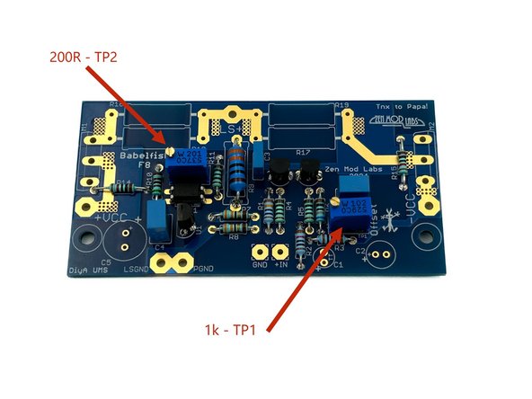
It is critical to identify and separate the two values of the potentiometers.
-
The potentiometer marked with a "102" is the 1k pot.
-
The potentiometer marked with a "201" is the 200R pot.
-
Install the 1k pot for TP1
-
Install the 200R pot for TP2
-
Photo 3 - Pots Installed
-
-
-
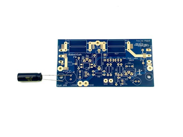
Verify the orientation of the electrolytic capacitors! The negative side a.k.a. the cathode is indicated with a band. The cathode lead is the shorter of the two leads. The positive side a.k.a. the anode is the longer of the two leads.
-
Photo 1 - Long lead goes into the hole marked with the +.
-
Install C1, C2, and C5
-
Photo 2 - Electrolytic caps installed
-
-
-
If you do not have a precision DMM known to work at lower resistances, it is recommended to trust the color bands on the resistors.
-
It is advised to raise the 3W resistors above the board a few mm. Use anything you may have available as a spacer.
-
Install R17 - Brown, Black, Gold, Gold - 1R
-
Install R18 - Yellow, Purple, Silver, Gold - 0R47
-
Install R19 - Brown, Green, Gold, Gold - 1R5
-
Install R16 - Blue, Gray, Silver, Gold - 0R68
-
Photo 1 - Large resistors installed.
-
-
-
By this point, if you haven't already, take a break and triple check your work.
-
Wise and careful builders will have noted that each and every part except the output MOSFETs have been verified, installed, and inspected.
-
This is also a perfect time to clean the back of the boards if you haven't been meticulously cleaning each joint as part of your inspection process. If you're using most popular solders, the boards don't strictly require cleaning, but it is much easier to inspect the joints if they're clean. Plus, it looks nice.
-
Note - 99%+ Isopropyl Alcohol and Kimwipes were used to clean the boards in the photo; nothing aggressive or toxic.
-
Photo 1 - Dirty
-
Photo 2 - Clean.
-
-
-
Wire can be a controversial subject. Choose your favorite, and others will do the same. The recommendations below are excellent choices if you don't already have a favorite.
-
DC Supply and Speaker Wiring
-
Stranded 18AWG or larger. Solid core wire is not recommended. The boards will comfortably allow 16AWG.
-
Silicon or PTFE insulation is nice to have in the case of a wandering soldering iron tip. Silicon tends to be more flexible at the expense of twists wanting to untwist. PTFE tends to be a bit more stiff, but twisted wires will generally retain their shape.
-
Input - 20 to 30 AWG. Copper or Silver. Twisted pair or shielded coax. Solid Core or Stranded. A common choice that works well is salvaged CAT5 / CAT6 etc. from spare ethernet cables.
-
-
-
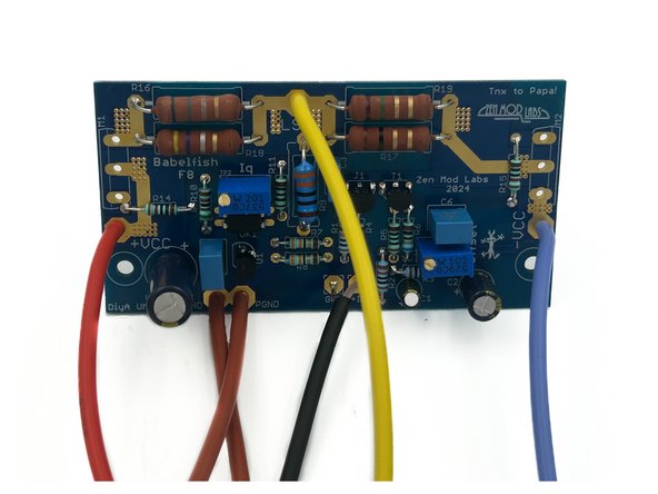
Choose your wire types and colors. It is wise to choose and use consistent colors that you can remember across your many future builds, particularly for power wiring. This example uses:
-
16 AWG multistrand with silicon insulation:
-
Red for +VCC (Positive DC Rail or V+)
-
Blue for -VCC (Negative DC Rail or V-)
-
Brown for LSGND and PGND (Loudspeaker Ground and Power Ground)
-
Yellow for LS+ (Loudspeaker Signal)
-
Mogami 2330 for +In and GND (Input Signal and GND)
-
-
-
You may want to do an initial layout with your chassis and PSU to estimate wire length. As one example, builders using the Universal PSU will require longer PSU wiring than those using the Simple Linear Bipolar Power Supply.
-
Cut your wires roughly to length and solder them to the amp PCBs. Err on the side of caution for wire length, and remember some wires will be twisted. Wire stretchers do not work well.
-
Photo 1 - All wires installed
-
-
-
The examples provided show:
-
3U heatsinks pre-drilled for the Universal Mounting Specification (UMS) pattern included with the Deluxe 3U chassis.
-
-
Board Mounting and MOSFET mounting hardware included in the Back Panel Parts Kit
-
-
-
As mentioned, this build uses the Deluxe 3U chassis. It is very similar for all Deluxe chassis with the pre-drilled and tapped UMS pattern.
-
If this is the first time you are using your heatsinks, ensure all tapped holes are free from burrs. You can use a finger tip to check. If there are burrs present, a piece of very fine wet sand paper, a fine file, or even a piece of green "Scotch Brite" pad will likely remove them. Be careful that you don't gouge the sink or damage the threads.
-
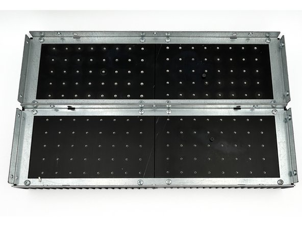
Make certain that you have the heatsinks properly aligned before assembly. Ensure that the two ends with shortest distance from the holes to the edges are joined at the middle.
-
Photo 1 - Two proper heatsink assemblies. Ignore the additional bolt. The heatsinks have been used for multiple projects.
-
Assemble both sets of heastinks using the parts provided with your chassis.
-
-
-
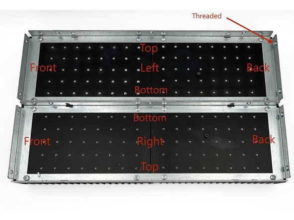
The heatsinks have a back and front. Once you choose left and right, they now have a top and bottom. It is generally preferred to have the input wiring toward the top. The threaded holes in the brackets are for mounting the back panel.
-
Photo 1 - Heatsink orientation.
-
Place a PCB on the heatsink in the center. It should be quickly evident that the two mounting holes in the PCB line up with the holes on the heatsink (YAY UMS!). If they don't line up perfectly, triple check your work.
-
Noting where your boards and MOSFETs will mount, ensure each hole is free from debris. Gently ensure that an M3 bolt will easily thread into the holes. If the screw binds, do not force it. Gently back it out, and start again. Do this until you can easily thread an M3 bolt for each hole.
-
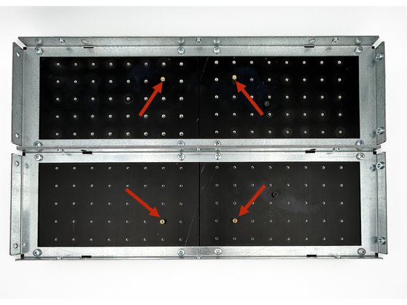
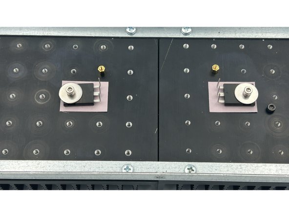
Thread four brass standoffs into the heatsinks as shown.
-
DO NOT over-tighten the standoffs. Overtightening can result in stripping the threads in your heatsinks or breaking the standoff, and you will be VERY sad. Firmly finger-tight is perfect. If the threads stick, back it in and out. A little lubricant may help also.
-
Photo 2 - Standoffs threaded into heatsinks.
-
-
-
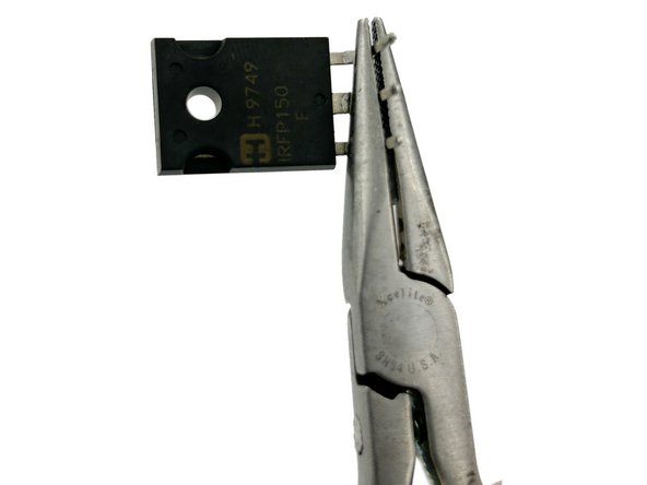
Photos 1, 2, and 3 - It is simple to get a proper bend in the MOSFET legs, but care must be taken. These photos illustrate a proper sequence. The part is held just below the narrowing point in the legs, and the legs are bent to 90 degrees.
-
Ensure that the lettering is up and the metal tab is down. You will bend toward the lettering. It is easy to adjust the angle slightly, but bending them back in the entire opposite direction may result in premature failure due to metal fatigue.
-
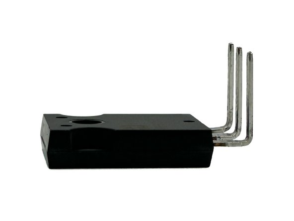
Bend all three leads of your MOSFETs to a 90 degree angle as shown. They don't need to be perfectly 90 degrees. Just get it close.
-
-
-
The MOSFETs are mounted to the heatsinks using M3 bolts, fender washers, and split washers from the back panel parts kit. Keratherm is the insulator of choice. The correct MOSFET mounting holes can be found by laying the PCB onto the standoffs and inserting a MOSFET.
-
All builders have their own sequence. One that works well for many is:
-
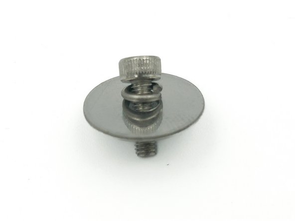
Place the split washer and the fender washer over the bolt.
-
Photo 1 - The split washer sits against the head of the bolt.
-
Place the MOSFET over the bolt with the tips of the legs toward the head of the bolt.
-
Gently place a piece of Keratherm over the bolt.
-
Gently thread the bolt into the heatsink. Align the Keratherm under the MOSFET. Tighten the bolt leaving it loose enough to rotate the MOSFET.
-
Photo 2 - MOSFETs mounted loosely to the heatsinks.
-
-
-
Gently slide the PCBs over the MOSFET legs.
-
Mount the PCBs to the standoffs using the short M3 bolts in the back panel parts kit and an M3 washer. There is no reason to over-tighten.
-
Photo 1 - Short M3 bolt and M3 washer.
-
Tighten the MOSFET mounting bolts ensuring that the Keratherm pads stay completely under the MOSFETs.
-
Avid DIYers that check spec sheets and have every tool available will use a torque wrench and tighten the bolts to precisely 1.1Nm. 0.9Nm to 1.2Nm is common. Most DIYers will tighten them to just over finger tight until the split washer compresses. It's not as tight as you may think. Don't overdo it.
-
Photo 2 - Boards Mounted and MOSFETs secured
-
-
-
Photos borrowed from F5M guide, but the process is exactly the same.
-
It is critical to check the resistance from the heatsink (chassis / mains earth) to each pin of the MOSFETs prior to soldering them into place. The metal back of the MOSFET is the drain, and it must be electrically isolated from the heatsink.
-
Check the resistance between the two bolts mounting the MOSFETs. It should be less than a few Ohms. If not, DO NOT proceed.
-
Photo 1 - Meter set to resistance. Probes placed between MOSFET mounting screws.
-
Note - You are measuring to ensure that the two heatsink sections are connected electrically to what will be established as "chassis ground" / mains earth. This is critical to safety.
-
Check the resistance from all 3 of the legs for both MOSFETs to the head of the screw mounting the MOSFET.
-
If the reading is not O.L (over limit) or in the MOhm range, check that your insulating pads are covering the entire base of the MOSFETs. DO NOT proceed if you do not measure in the MOhm range or your meter does not read O.L. (over limit).
-
Photo 2 - Meter set to resistance. Probes placed on mounting screw (mains earth / chassis GND) and pin 2 (drain). O.L (A very high resistance) is a proper result.
-
-
-
The solder joints for the MOSFETs are exposed to thermal stresses over the long life of a properly built amplifier. It is important to ensure good solder flow and a proper joint. The thermal mass / area of the joint is relatively large. The use of flux and/or a slightly higher soldering temperature or larger tip is recommended.
-
It's best to be fast. If you're joints are taking longer than 5s, you have too small a tip and/or too low a temp.
-
Solder the three pins of each MOSFET to the amp PCBs.
-
Photo 1 - A properly soldered MOSFET.
-
Double check the resistance measurements from Step 32. It's rare, but things can shift. It takes <30s, and it's critical; so why not?
-
Set your amp board heatsink assemblies aside for now.
-
-
-
You've now completed your amplifier boards and done the initial, critical checks. It's a perfect time to congratulate yourself and take a break.
-
-
-
The PSU used for this guide is the Simple Linear Bipolar Power Supply. For more information, check the diyAudiostore and review the build guide.
-
PSU assembly and testing is not included in this guide. It is advisable to use at least 150VA of transformer power per channel, with 18+18Vac or 36Vct secondaries. This will result in +/-24Vdc rails nominally with no load and result ending somewhere at +/- 22V5dc. A little higher or lower is no issue.
-
Ensure that your power supply is fully tested and meets all requirements before proceeding.
-
Using any linear PSU of this type involves potential exposure to mains AC. Exposure to mains AC can be lethal. It is critical to follow proper safety procedures. If you are unsure how to proceed, seek qualified assistance.
-
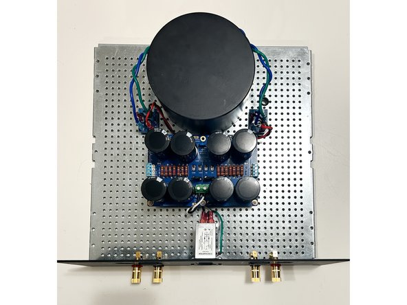
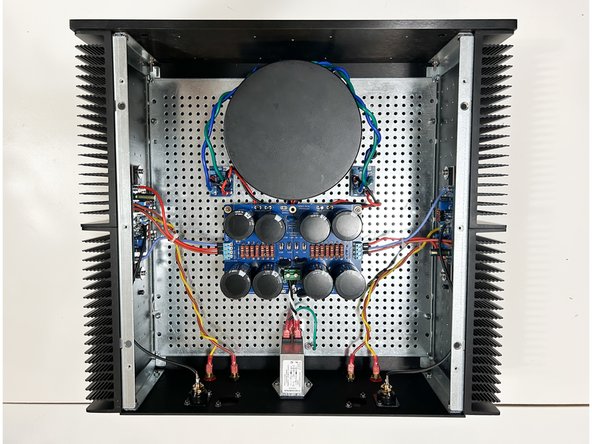
Photo 1 - The Simple Linear Bipolar Power Supply mounted securely to the perforated base plate. The back panel is fully assembled minus the input RCA jacks.
-
-
-
Everyone develops their own build sequence and chooses whether they will use terminations or direct solder their wiring. For this guide, bootlace ferrules and Euroblocks were used for the PSU connections. Female blade connectors were used for the binding posts. The inputs were direct soldered.
-
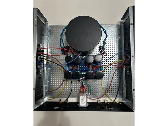
Collect the heatsink / amplifier board assemblies. Mount the heatsinks to the perforated baseplate using the hardware provided with the chassis.
-
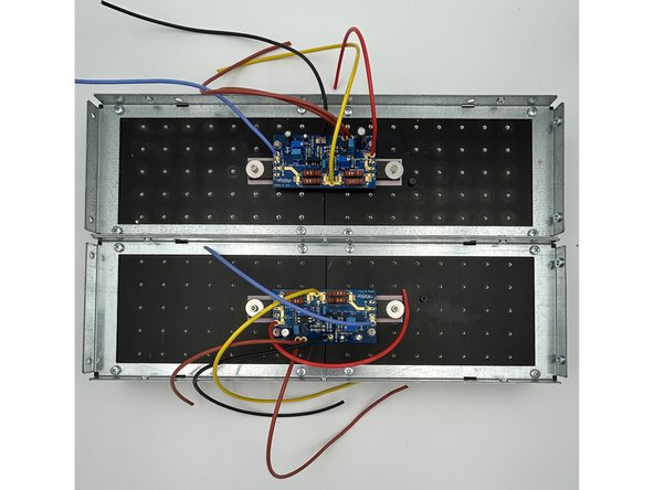
Photo 1 - Initial wiring with longer-than-necessary wiring.
-
Estimate the wire lengths from the amp boards to the PSU and to the speaker binding posts. You can try to get it exact if you like, but it is safer to have a little excess wire. Trim and terminate (as appropriate) the +VCC, -VCC, LS+, and both GND wires.
-
Estimate the wire length from the amp boards to the RCA input jacks. Solder the input wiring to the RCA input jacks. Install the input jacks to the back panel. Install the back panel to the heatsinks using the hardware provided with the chassis.
-
Connect all wiring to the power supply and binding posts as appropriate. Those that choose to direct solder each wire on both ends will likely want to wait until each amplifier board is tested separately before soldering the wiring to the PSU. See step 39.
-
Be extremely mindful of the +VCC (V+) and -VCC (V-) connections to the PSU. Reversing them will result in "magic smoke".
-
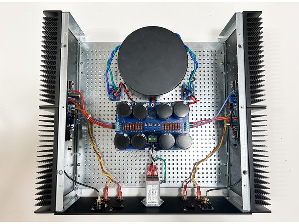
Photo 2 - All wiring in place. Perforated base plate and back panel attached to heatsinks.
-
-
-
If you have a brand new chassis, the feet should be installed prior to attaching the bottom panel to the heatsinks.
-
If you're going to have LEDs on your front panel, now is a great time to check the wiring length and finalize any connections.
-
Attach the front panel and bottom panel to the heatsinks using the hardware provided with the chassis.
-
Note - In this guide 4 x M4 threaded rods (commonly available) were used along with Keps nuts to secure the front panel to the heatsinks. The standard M4 bolts provided with the chassis work wonderfully, but some may find alternate hardware easier to access and tighten securely depending on the build sequence and choices that may restrict space.
-
Photo 1 - The amplifier is essentially complete (minus the top panel).
-
Triple check all wiring / connections paying particular attention to the PSU wiring.
-
-
-
It is strongly recommended to check each amplifier board individually for initial functionality.
-
One DMM is necessary. Two are strongly recommended.
-
One DMM should have "j-hook" style probes or a style of probe that allows the builder to keep both hands free and allow a secure attachment to resistor leads without touching adjacent components.
-
A variable transformer is recommended, but not strictly necessary.
-
The use of an enclosed / protected screwdriver similar to a Bourns H-90 is strongly recommended to adjust TP1 and TP2. At a minimum, a non-conductive screwdriver should be used.
-
You will be making adjustments in proximity to mains voltage. Ensure that you cannot make accidental contact with mains voltages. Follow all safety precautions including, but not limited to, using proper DMM probes and a proper tool to adjust the trimmers.
-
Please read Steps 39 through 41 through repeatedly until you are confident in your process. Ask questions in the forum if there are any concerns or if you need clarity.
-
-
-
With the mains power disconnected, wire one channel of the amplifier board to the power supply; +VCC (V+), -VCC (V-), and PSGND (GND).
-
If both channels are connected, disconnect the V+ and V- from one amplifier board at the PSU.
-
Connect the mains through the variable transformer (as applicable).
-
Ensure the appropriate fuse is installed, particularly if the PSU was recently tested using a low amperage fuse.
-
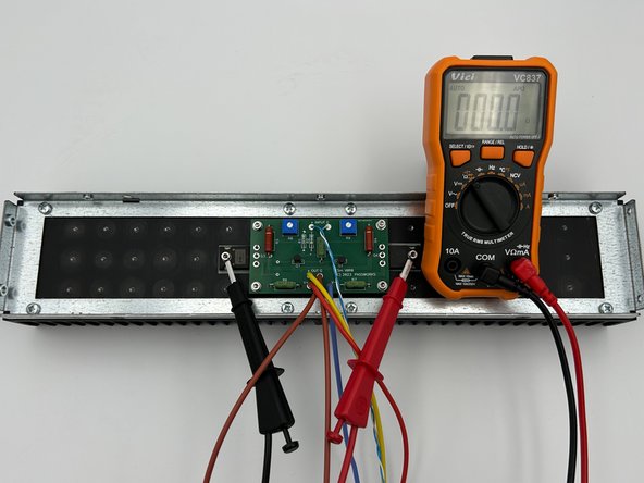
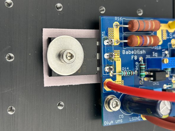
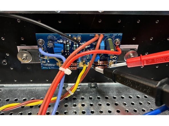
Connect one DMM across R18. Ensure the DMM is set to measure DCV ranging from 0V to 1V. Precision at a mV level is needed.
-
Connect one DMM across the binding posts for the same amplifier channel. Ensure the DMM is set to measure DCV ranging from 0V to 1V. Precision at a mV level is needed.
-
Photo 1 - Probes Across R18.
-
-
-
It is critical that the PSU is built properly and is delivering roughly +-25 to 26VDC (unloaded) if it is an unregulated PSU. If you are unsure, double check the PSU voltages before proceeding.
-
Validate one more time:
-
V+ and V- and GND are properly connected from the amplifier boards to the PSU.
-
Variable transformer is set to minimum voltage (if applicable).
-
One DMM is to set to DCV and probes are across R18.
-
One DMM is to set to DCV and probes are across the binding posts.
-
Make sure you are in a place where you can de-energize (turn off) the circuit quickly and safely if you smell smoke, see sparks, or observe anything concerning. Do not have any part of your body near the circuit when applying power. Ensure you are wearing proper personal protective equipment including saftey glasses.
-
Disconnect the power if you see or smell smoke, if you see sparks, or if the voltage across R18 exceeds 600mV.
-
-
-
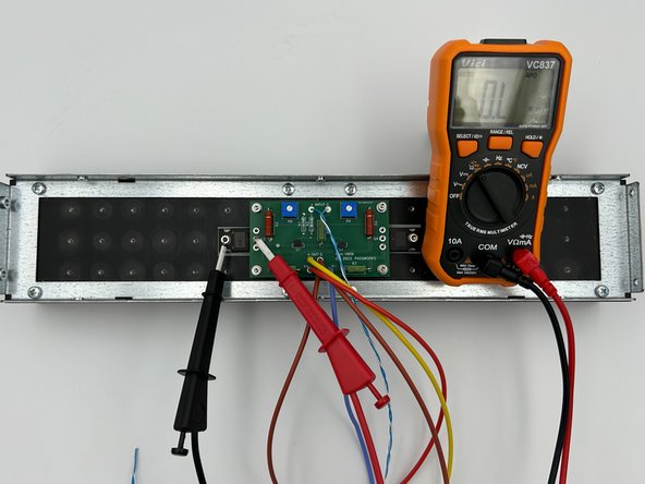
Power the circuit (Turn it on). If you are using a variable transformer, slowly increase the voltage until you notice a voltage across R18.
-
Adjust TP2 in both directions. The voltage across R18 should increase and decrease. Note which direction of rotation results in the absolute value of the voltage increasing and decreasing
-
Continue increasing the voltage from the variable transformer until you reach full mains voltage. If the voltage across R18 exceeds 500mV before full mains is reached, adjust TP2 until it is below 500mV.
-
Adjust TP1 in both directions. The voltage across the binding posts should change. Note which direction results in the voltage going more positive or more negative.
-
If either pot does not result in the voltages changing appropriately, and/or if the voltage across R18 cannot be set to below 500mV, disconnect the power, pause, troubleshoot and/or seek assistance.
-
Remove power to the circuit. Safely disconnect the V+, V- and GND connections from the amp board to the power supply.
-
Repeat steps 39-41 for the other amplifier board. Once you've validated both boards operate appropriately, move on to step 42.
-
-
-
Congratulations. You're most of the way there. It's the perfect time for another break and a happy dance. Chances are, you're going to hear music soon.
-
-
-
Expect to spend at least 2 hours setting the final bias and nulling the offset of both channels. Do not rush.
-
The bias current is very stable and likely will not vary more than 10mV at typical temperature changes from ambient to operational. The DC offset is temperature dependent and will require the amplifier to be at thermal equilibrium at full operating temperature to set properly.
-
To achieve 1A8 Iq for each channel, the voltage target across R18 will be 500mV +/- 10mV.
-
DC offset should be as low as practical. The target voltage across the binding posts is 0mV +/- 10mV.
-
-
-
In order to allow as little noise into the circuit as practical while setting the bias and offset, it is advised to short the inputs during the bias and offset adjustments.
-
You can short the inputs any number of ways. Two simple methods are:
-
Using "crocodile leads" to short the inner barrel of the RCA to the GND tab.
-
Using a set of "shorting plugs" fashioned from old RCA connectors.
-
Strip the outer insulation.
-
Twist the leads together.
-
Short the inputs to both amplifier channels
-
Validate by ensuring there is only a fraction of an ohm resistance between the Input (+) and Input (G) pads on the PCB.
-
-
-
Connect the other amplifier board to the PSU. Both amplifier boards should now be connected to the PSU.
-
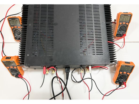
If 4 DMMs are available, connect additional DMMs across R18 and across the binding posts of the 2nd amplifier board.
-
Triple check that V+, V-, and GND are connected properly for both boards.
-
Remove the variable transformer or DBT (as applicable). Full voltage mains power should be connected directly to the PEM.
-
Place the top cover gently on top of the amplifier taking care to not pull on your DMM leads. Turn on the amplifier.
-
-
-
The goal of this step is to set the final bias and offset. It is wonderful if you have 4, DMMs. If not, it will just take you a little longer.
-
PLEASE DO NOT RUSH. IT IS NOT RECOMMENDED TO MOVE PROBES BETWEEN CHANNELS WITH THE AMPLIFIER UNDER POWER. IF YOU DON'T HAVE 4 DMMs, PLEASE DO ONE CHANNEL AT A TIME
-
As mentioned, the bias current is very stable. However, the offset will change as the output devices warm up. The amplifier must be at thermal equilibrium.
-
Turn on the amplifier.
-
Allow the amplifier to come to temperature for at least 30 minutes while monitoring the DMMs to ensure the voltage across R18 does not exceed 550mV. If the voltage begins to approach 550mV adjust TP2 to reduce the voltage.
-
Remove the lid. Carefully and quickly adjust TP2 until the voltage across R18 is as close to 500mV as you can achieve. Put the lid back on. Wait at least another 5 to 10 minutes. Remove the lid. Tweak. Replace the lid. Repeat until the voltage does not wander outside the set tolerances or until you're happy.
-
Remove the lid. Carefully and quickly adjust TP1 until the voltage across the binding posts is as close to 0V as you can achieve. Put the lid back on. Wait at least another 5 to 10 minutes. Remove the lid. Tweak. Repeat until the voltage does not wander outside the set tolerances or until you're happy.
-
Photo 1 - Close enough to 500mV on both channels and less than 10mV of offset. No changes in bias or offset for over 20 minutes. Success!
-
-
-
It is bad luck to screw the lid down before testing the amplifier with music.
-
Use a pair of test speakers (speakers that you won't mind if they are damaged). A phone, tablet, or any other battery-powered source is appropriate for initial testing.
-
Ensure the power is off. Connect a source and ensure the volume is all the way down. Connect your test speaker(s).
-
Turn on the amplifier. Turn on your source. Adjust the volume, and play some music. Listen for any noticeable distortion or unpleasant sounds. It is recommended to run the amplifier for a day or two on test speakers. Check it with a mains powered source. Monitor the bias and offset periodically to ensure it is stable.
-
Ambitious DIYers may take this opportunity to also do some objective measurements.
-
Video 1 - It's a 'Lovely Day'.
-
Once you know the amplifier is stable over a period of days, screw down the top panel, place the amplifier in its new home, and enjoy your new Babelfish F8 for years to come.
-


Congratulations on building the Babelfish F8
A few things before you run off and start another project:
- This is a build guide by DIYers for DIYers. If you have any suggestions for improvement, notice any errors, or think something could be clarified, please post in the forums. Someone will be looking.
- Please post some pictures of your build in the forum. Nothing makes us happier than seeing completed builds and the creativity of DIYers around the world.
- Make sure to go to the forums and thank Zen Mod for another amazing project.
- Last but not least, please click the button below if you completed the amp. It really helps the data dorks.
Cancel: I did not complete this guide.
2 other people completed this guide.