
-
-
Guide under construction.
-
The body of the guide is 90% complete at this time.
-
-
-
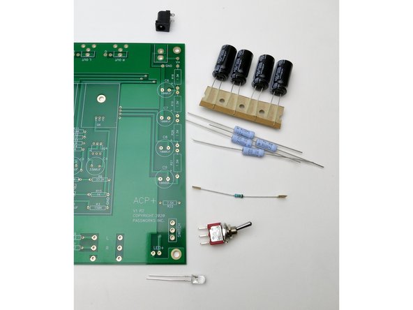
A fantastic kit of parts available with all the components, hardware, fasteners and PSU.
-
Although some of the aesthetics of the parts do not match the photos in the guide, they are electrically and qualitatively a 1:1 match.
-
-
-
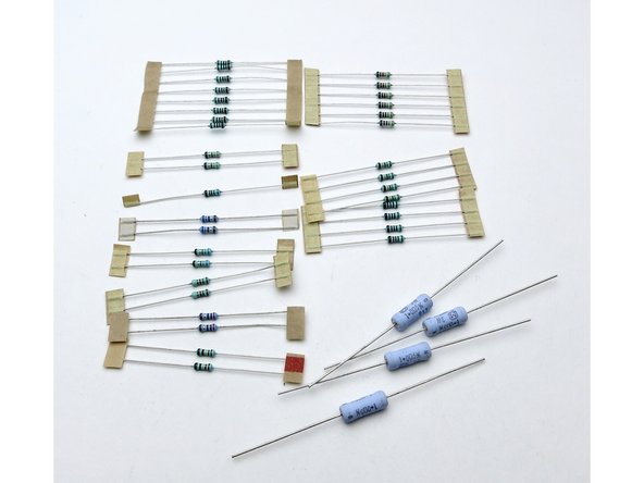
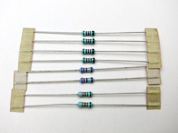
Photo 1 - Resistors
-
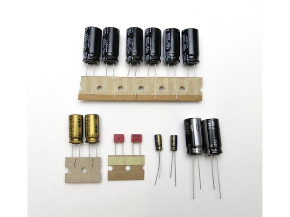
Photo 2 - Capacitors
-
Photo 3 - Semiconductors
-
-
-
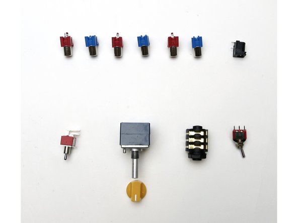
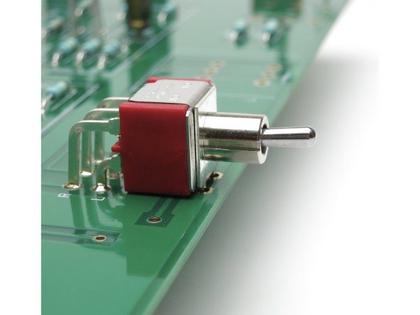
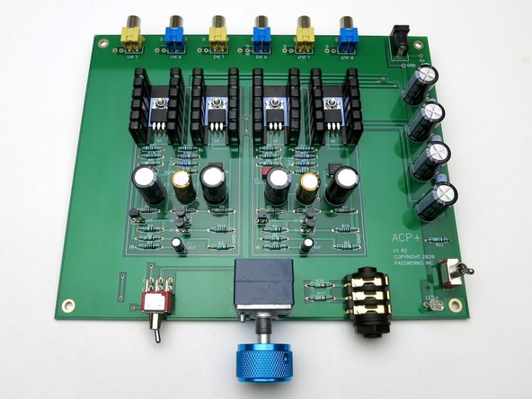
Photo 1 - Jacks, switches, and Potentiometer. (Red are incorrect style to fit PCB , this photo will be updated)
-
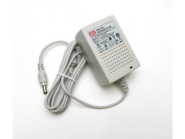
Photo 2 - Example 24VDC power supply with 5.5x2.1mm plug.
-
-
-
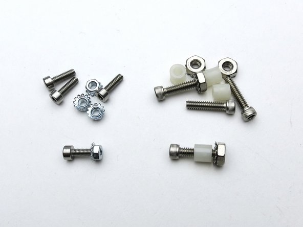
Large - Groundplane attachment bolts Small - Mosfet attach bolts
-
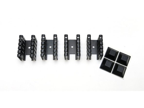
Heatsinks and stick-on feet
-
-
-
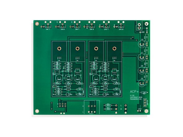
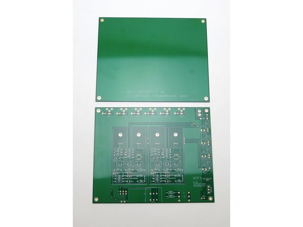
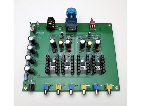
Circuit PCB
-
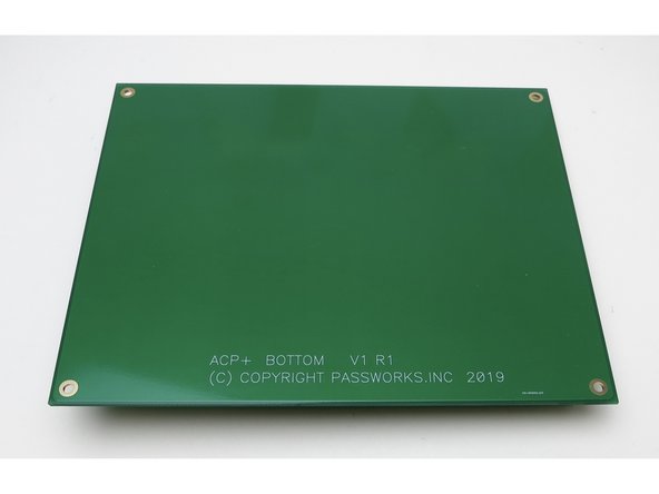
Ground Plane board
-
Both are the same size
-
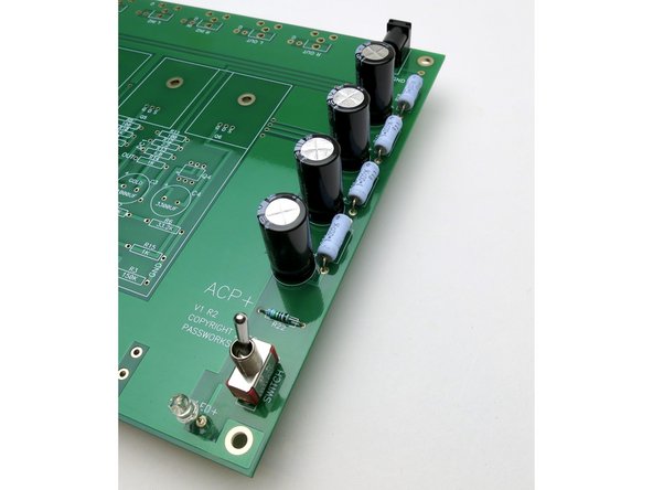
Note: If you plan on building this without a chassis (I.E., as shown...) you must use the ground plane.
-
-
-
Gather these components
-
Stuff PCB smallest to largest, resistors, then power jack,
-
-
-
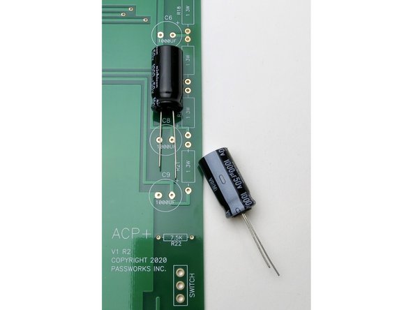
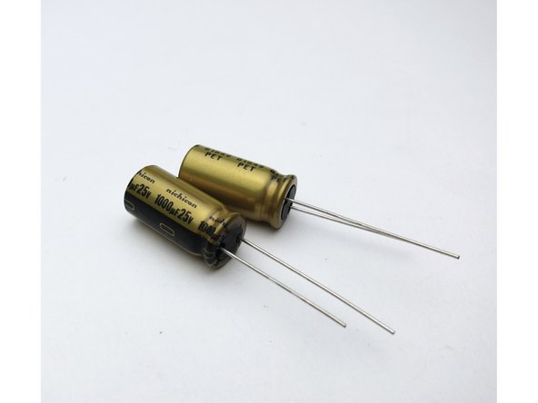
Capacitors are polarized.
-
The Negative side is marked on the can
-
The positive lead is longer
-
The PCB has a "+" marked for the positive lead
-
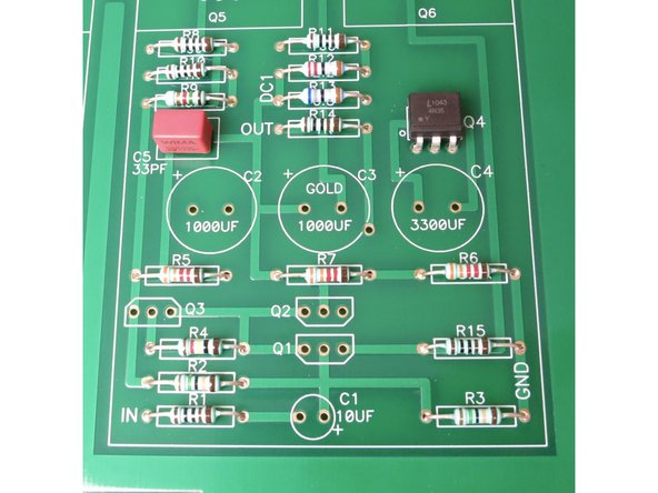
Finish stuffing PSU capacitors and watch polarity.
-
-
-
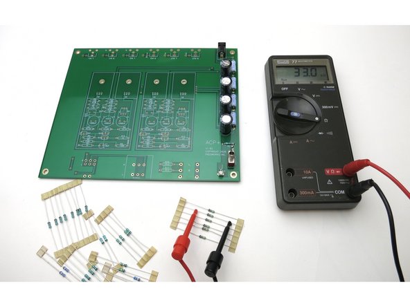
Add testing procedure
-
-
-
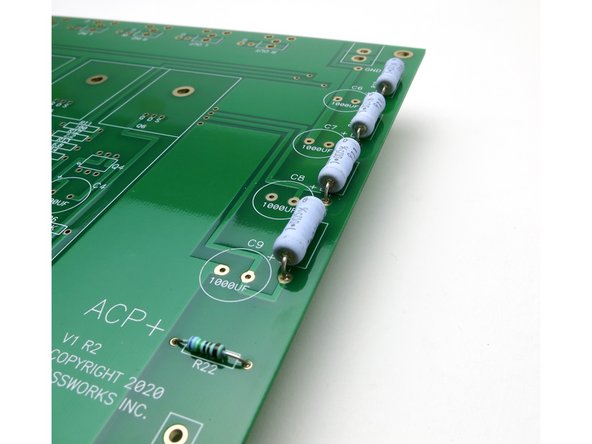
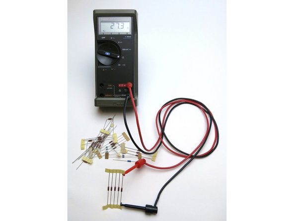
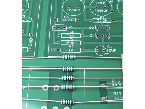
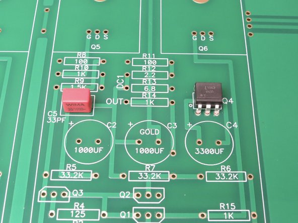
Measure all resistors before inserting into the PCB. This greatly reduces errors during construction.
-
-
-
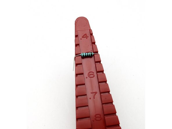
All smaller resistors are on a 0.5 inch lead spacing. A lead bender tool is recommended.
-
Remember, stuff resistors with the brown band to the right.
-
-
-
Stuff resistors with the slightly thicker brown band to the right.
-
-
-
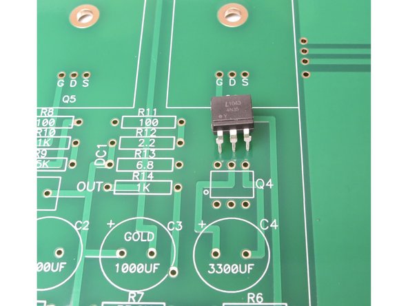
Optocoupler has a dot at pin 1, this aligns with dot on PCB
-
-
-
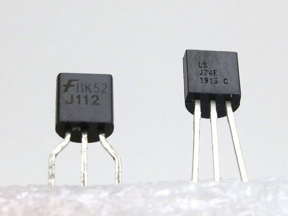
Left side J112.
-
Right side LSJ74.
-
J74s in this circuit need to be matched.
-
-
-
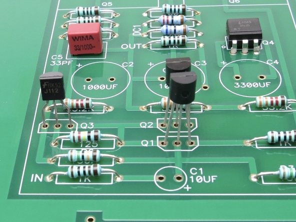
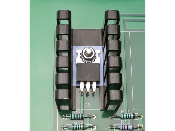
The flat of the transistors aligns with the flat of the transistor mark on the silkscreen.
-
Q1, Q2 are a matched pair of LSJ74
-
Q3 is a J113 selected for Vp of 2.5v, +/- 1v
-
-
-
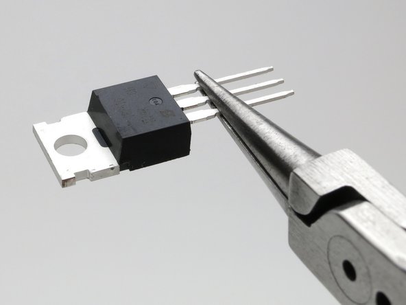
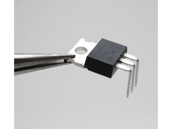
Bend legs down at point shown.
-
-
-
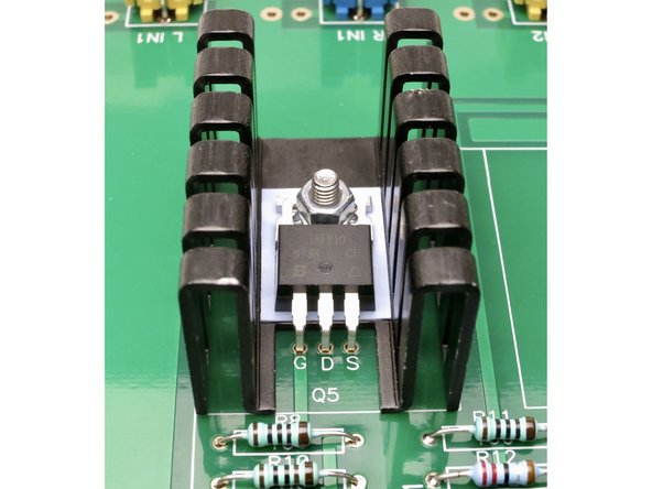
Thermal interface (pad or paste) not strictly required, but not a bad idea.
-
Mosfets do not need to be electrically isolated from the heatsinks.
-
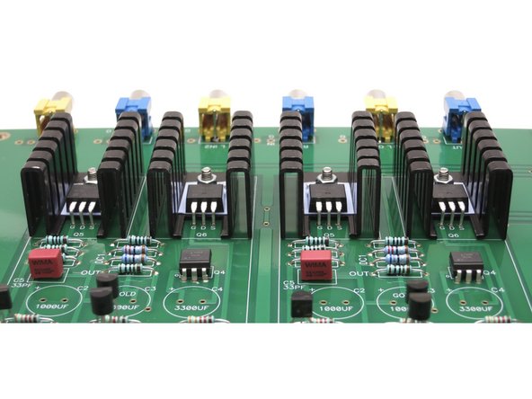
Make sure heatsinks are aligned and do not touch each other.
-
-
-
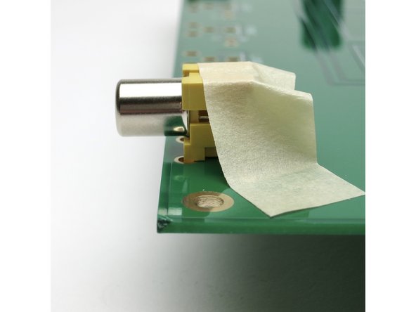
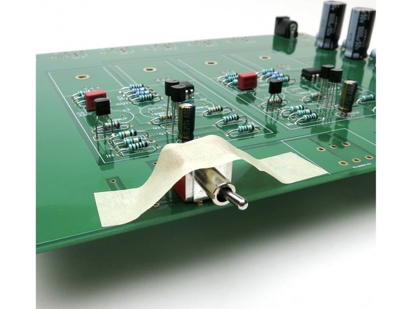
A bit of tape will hold the jack completely flat on the PCB for soldering.
-
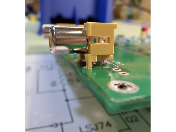
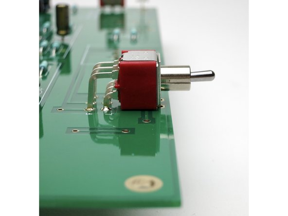
Photo 3 - Improper alignment. Make sure the jack is entirely flat on the PCB before soldering.
-
-
-
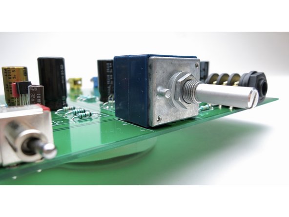
Maker sure potentiometer is flat on the PCB before soldering.
-
-
-
Make sure the switch is flat and flush with the PCB before soldering
-
-
-
Insert wisdom here.
-
-
-
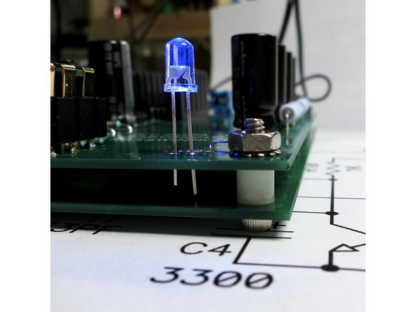
Screw from bottom, spacer in-between, nut on top.
-
-
-
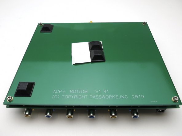
Place as shown
-


Cancel: I did not complete this guide.
11 other people completed this guide.