
-
-
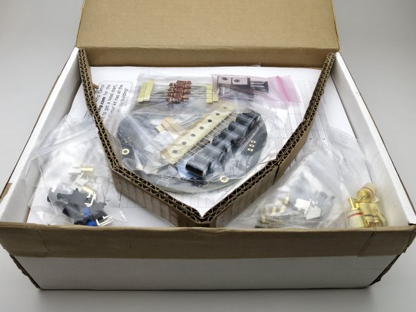
This is the build guide for the ACA Redux
-
-
-
Please read through this guide once or twice before building your amplifiers.
-
You can click into each photo if you need to see it full size.
-
-
-
All the pieces you need are included.
-
-
-
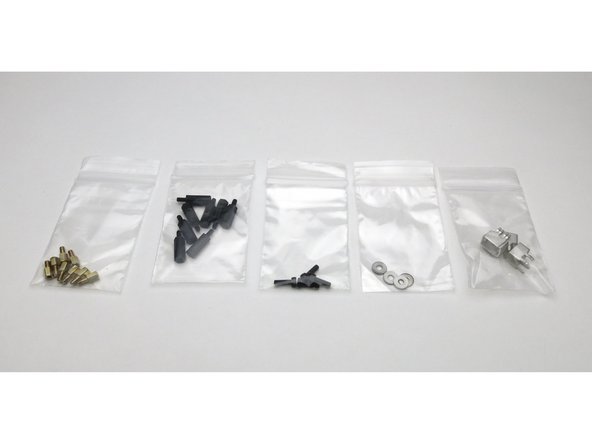
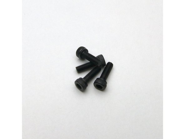
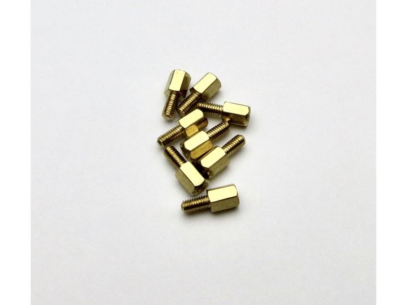
Starting with the hardware,
-
Photo 2 - M3 x10 for the power transistors.
-
Photo 3 - M3 brass standoffs, these go between the heatsink and the PCB.
-
-
-
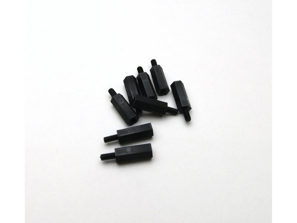
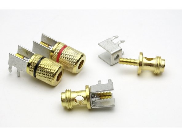
Photo 1 - M3 plastic standoffs, these are the 'legs' the amplifier stands on.
-
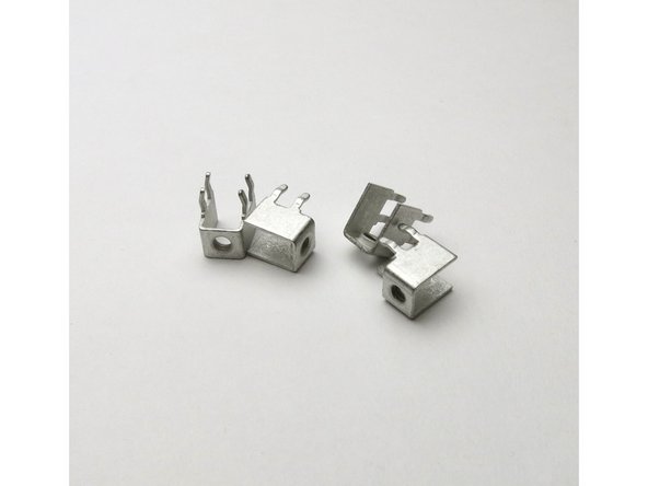
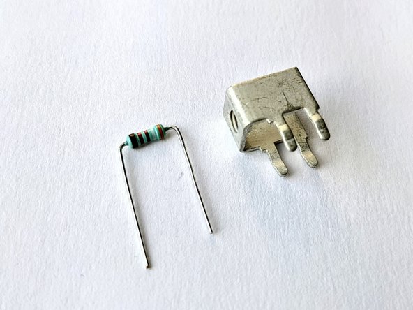
Photo 2 - PC mount M4 screw terminals, used for the speaker posts AND to bend the leads of the small resistors.
-
Photo 3 - M3 washers for securing the power transistors.
-
-
-
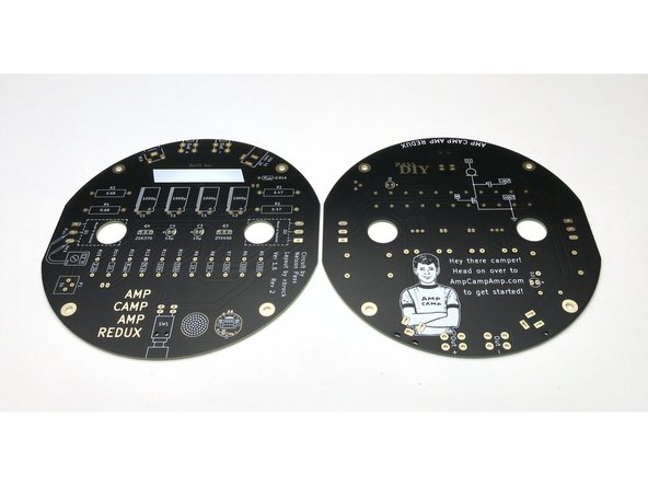
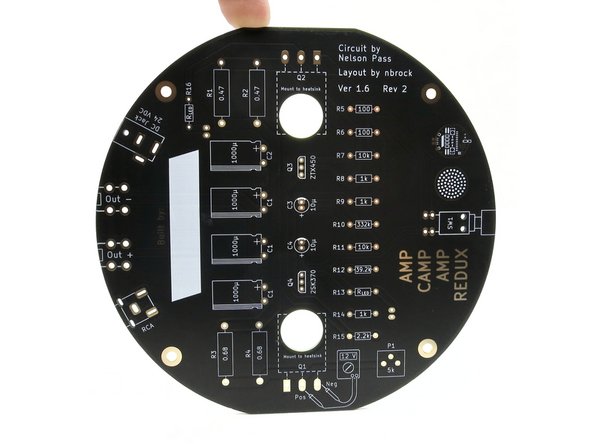
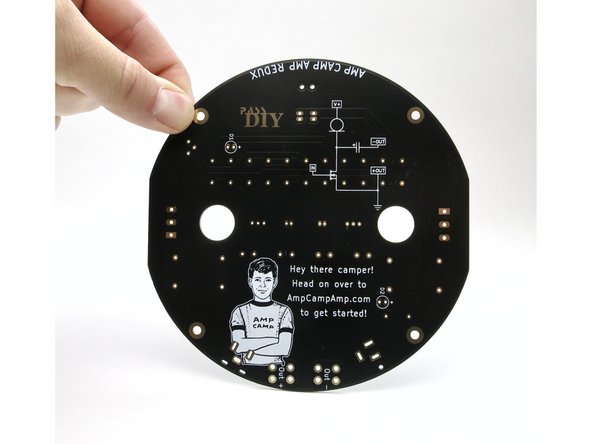
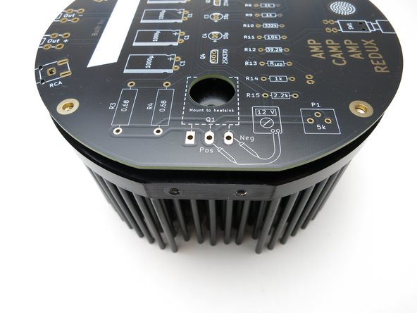
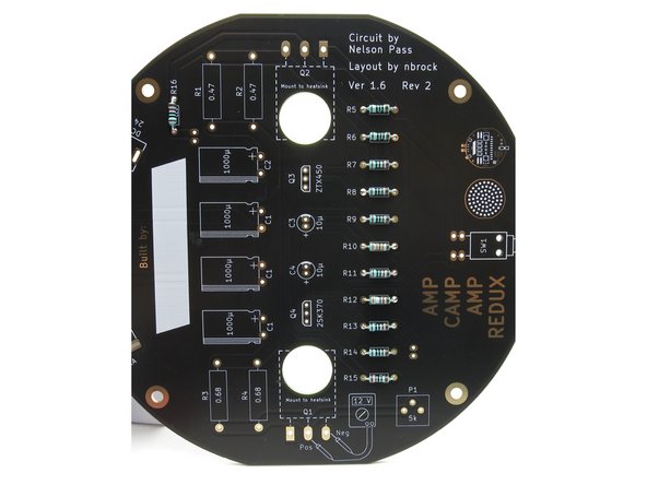
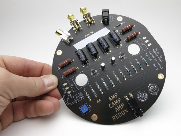
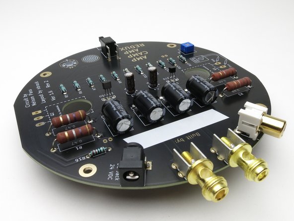
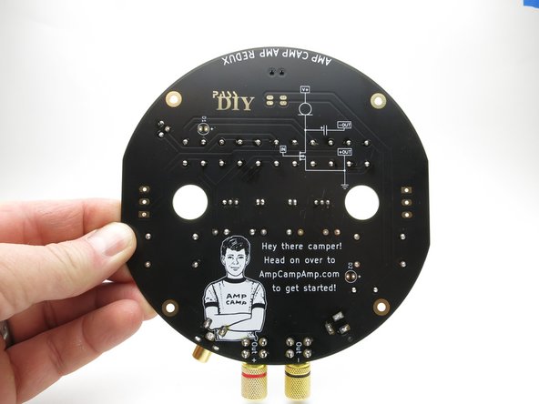
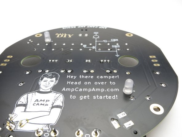
Here you can see the top and bottom of the PCB.
-
Almost all components are mounded on the side showing the component values. This side will be hanging down in normal operation.
-
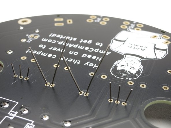
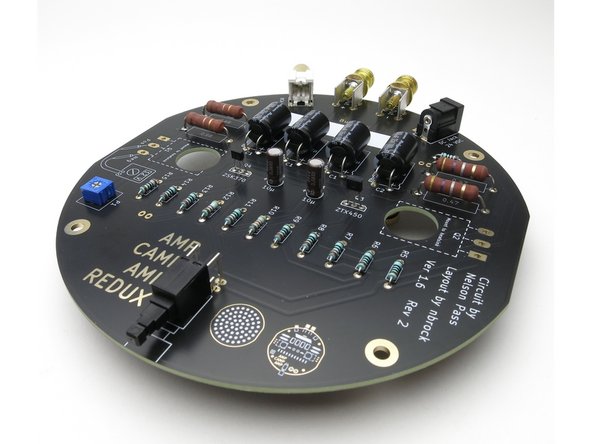
The side with the drawing of the Amp Camp Camper will mount only the LEDs, as they need to shine up through the pins of the heatsink. Neat!
-
-
-
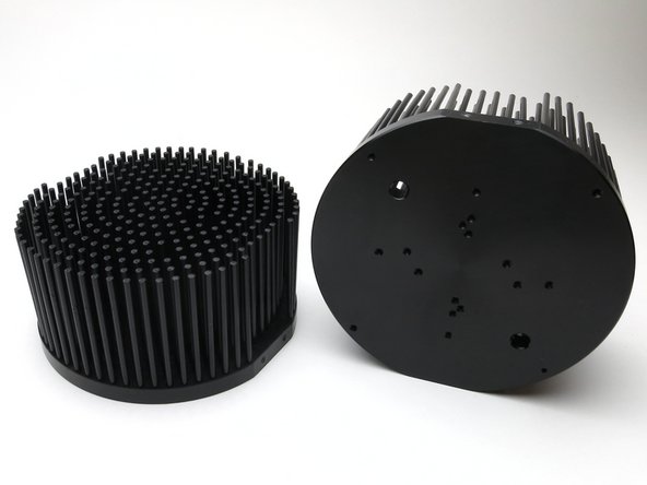
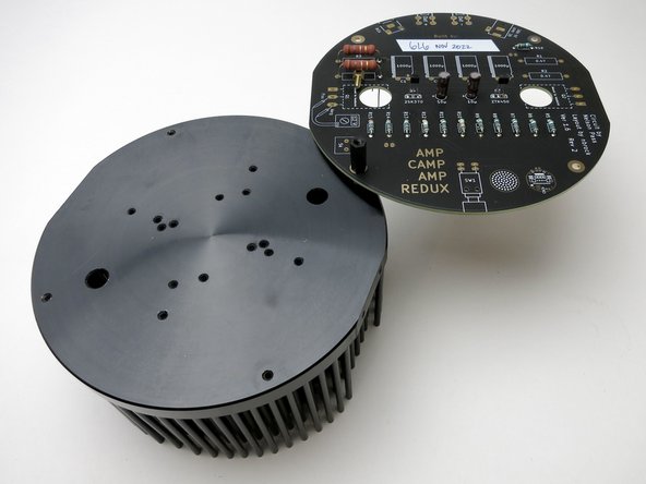
This heatsink was actually designed for a very large/bright LED lamp.
-
The PCB was designed to take advantage of the existing holes in the heatsink, requiring no drilling by the builder. A very smart design.
-
-
-
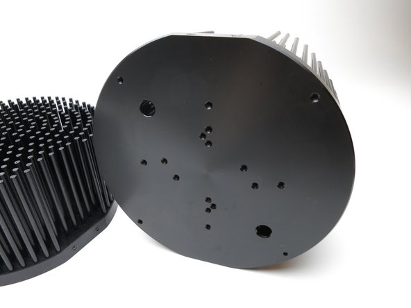
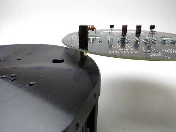
Notice that the PCB and the heatsink have 2 cut-off or flat edges. This will be more important later, but this is a good photo showing it.
-
When it is assembled these flat bits must be aligned.
-
-
-
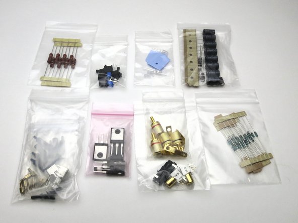
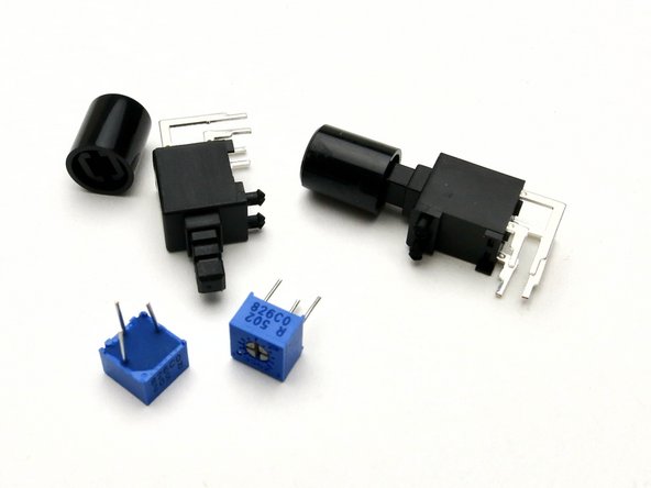
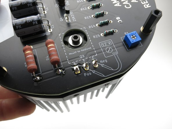
Photo 1 - Power switch and potentiometer.
-
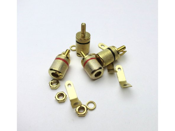
Photo 2 - Speaker jacks. The nuts, washers, and solder terminals will not be used.
-
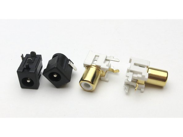
Photo 3 - DC power jacks and RCA (signal) jacks.
-
-
-
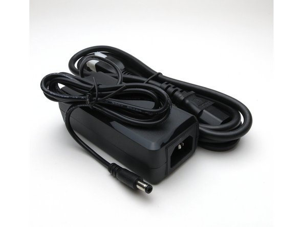
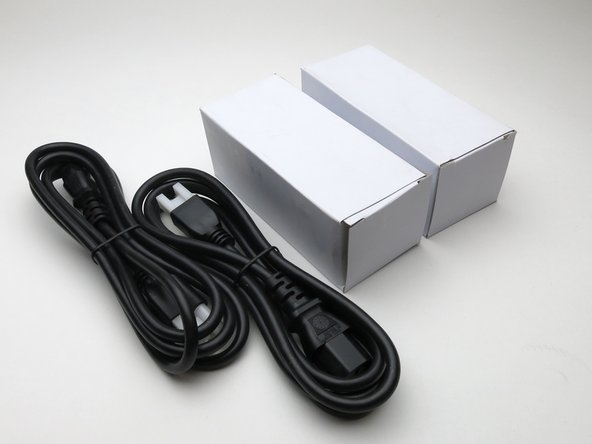
Included with the kit is a pair of 24V 2.5A DC power supplies. One for each channel.
-
These PSU are universal input, and have an IEC C14 inlet plug. Users in different countries need only to find suitable AC mains cords.
-
-
-
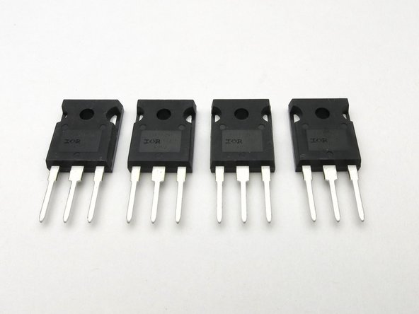
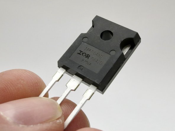
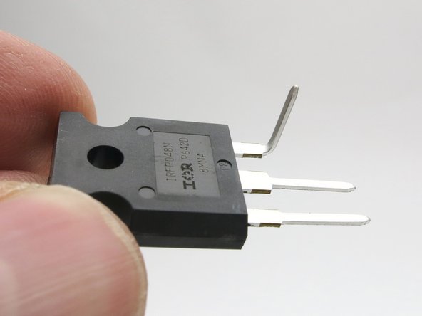
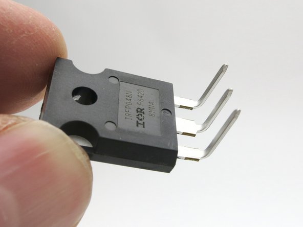
The TO-247 package power transistors are all the same, no matching or sorting required. Each amplifier will use 2.
-
-
-
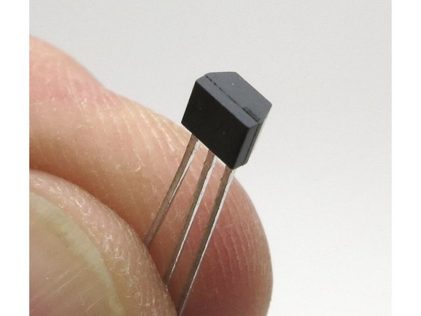
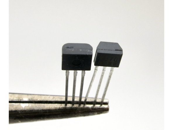
The smaller and more angular of the small-signal transistors is the 2SK370 N-channel Jfet.
-
This is used in position Q4
-
-
-
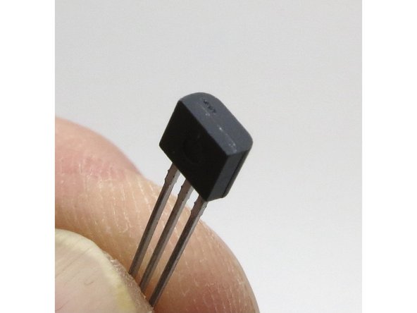
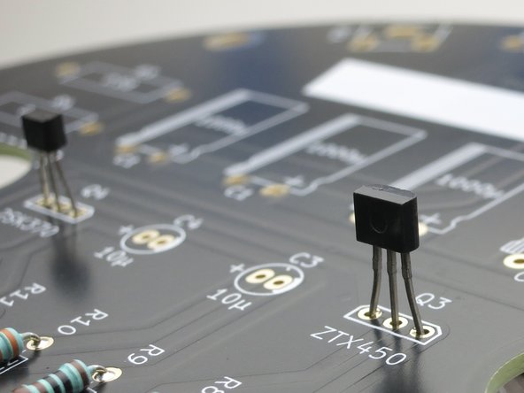
The slightly larger and smoother small-signal transistor is the ZTX450 N-channel BJT (Bipolar Junction Transistor)
-
This is used in position Q3
-
-
-
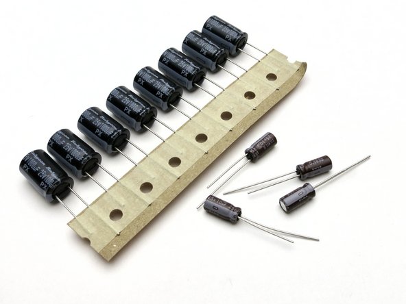
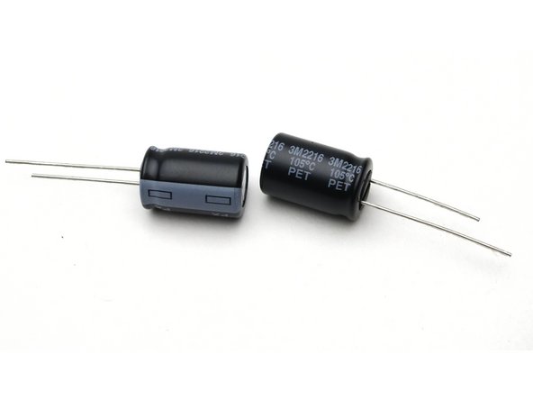
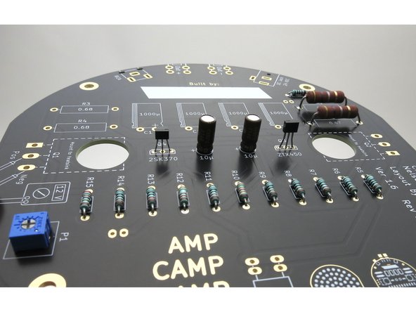
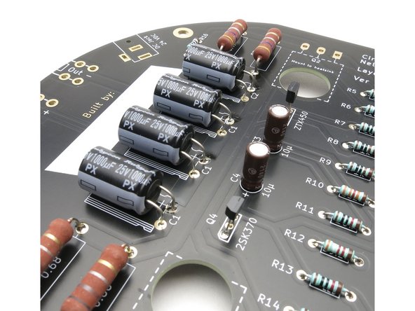
Included are (8) 1000uF capacitors. These are the larger caps, and used in positions C1 (3 per amp) and C2. (1 per amp)
-
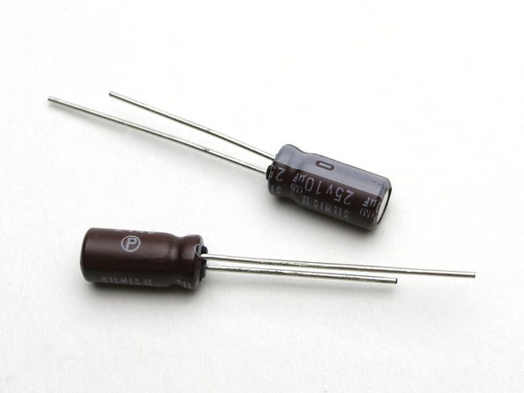
The smaller capacitors are 10uF, used in positions C3, C4.
-
Capacitors have a plus and a minus and are directional! The can has the - side labeled, and the longer leg is +.
-
-
-
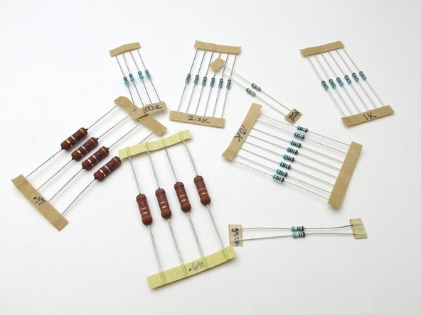
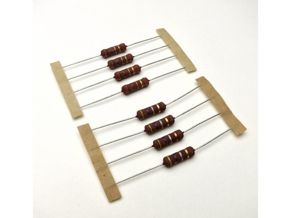
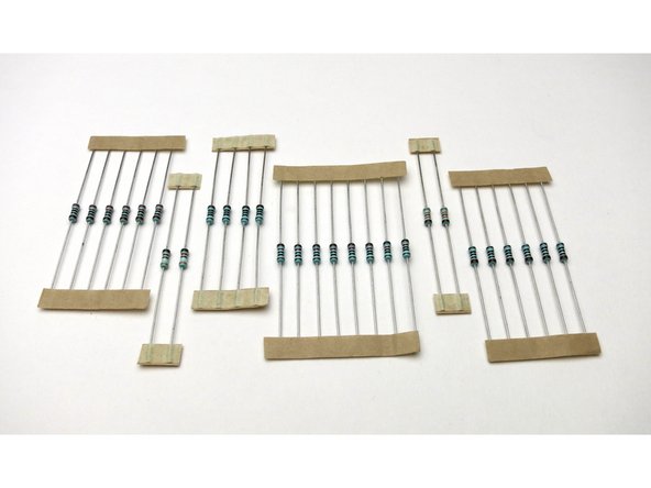
Resistors are packaged as shown.
-
There are extra 2.2K and 10K resistors. These are for R13 and R16. They set the brightness of the LEDs. 2.2K is brighter than 10K.
-
Please note that the resistor values are not labeled in the kit. This is a step for you to do later.
-
-
-
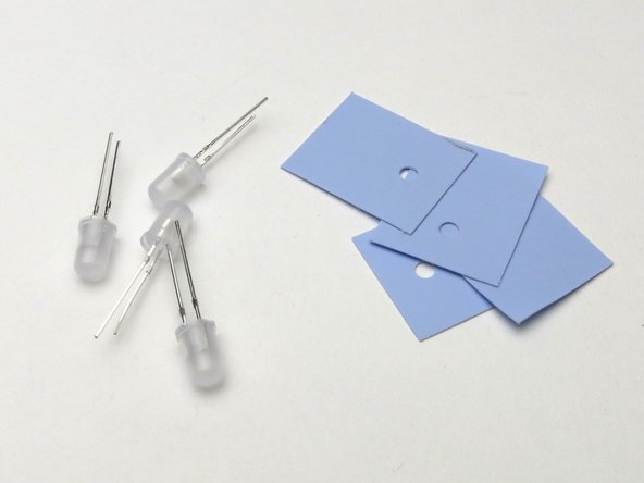
The blue insulator pads go in-between the power transistors and heatsink.
-
LEDs are used for power indication as well as illuminating the heatsinks.
-
-
-
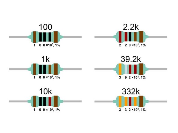
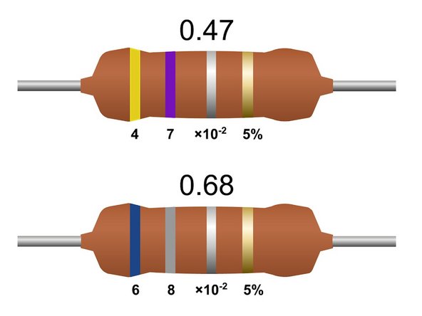
Resistor color codes.
-
-
-
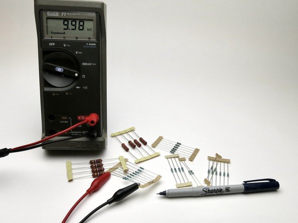
Measure all your resistors and label the tape.
-
The large resistors are very low ohms, and most multimeters will have a problem accurately measuring them. Refer to the reference and stripe codes.
-
-
-
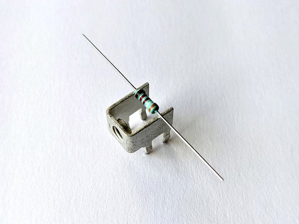
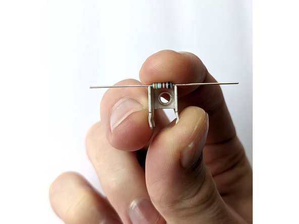
The solder terminals that will be used for the speaker posts will be used as a tool to bend the leads of the small resistors.
-
If you use this, the small resistors will be bent perfectly to the solder pads.
-
-
-
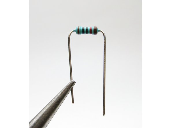
Bend small resistor leads as shown.
-
-
-
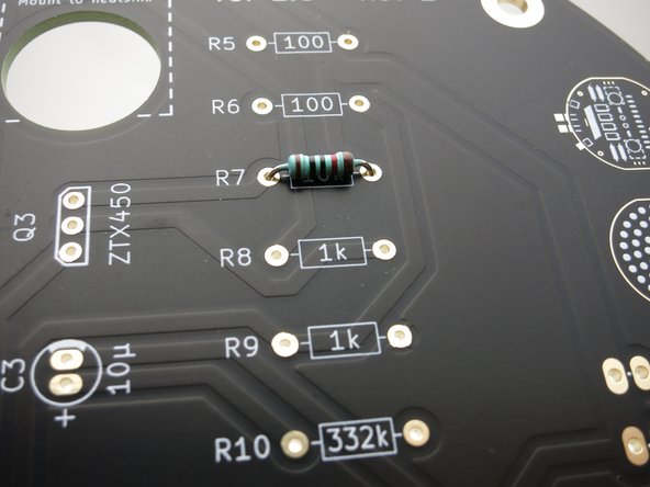
Take a resistor with the leads bent and insert it into its set of solder pads.
-
Make sure the resistor sits flat, and with the slightly thicker brown stripe to the right.
-
Neatness counts.
-
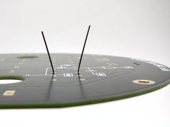
Flip the PCB and slightly bend the leads outwards so the resistor stays in place.
-
-
-
You can solder the resistors one-by-one, or do them all at once.
-
Once properly soldered, trim the leads.
-
-
-
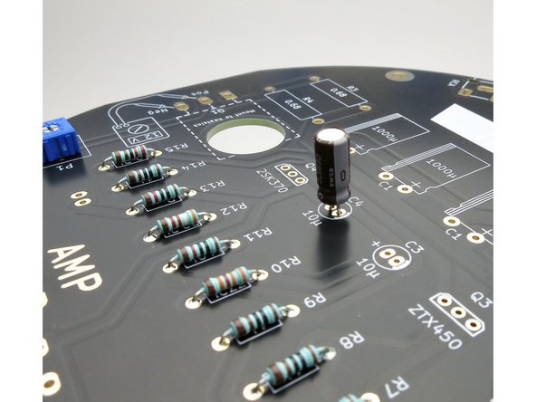
A photo of all the small resistors stuffed on the PCB.
-
Don't forget R16, it isn't grouped with the other resistors. (top left in this photo)
-
-
-
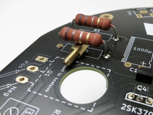
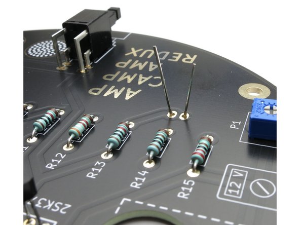
The Large resistors get warmer than the small and some space off the PCB will help with airflow.
-
You can use the brass standoff to gauge the space under the large resistors.
-
It helps to solder one leg from this side before flipping the PCB over... :)
-
-
-
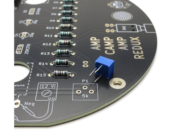
Potentiometer is keyed and cannot be inserted backwards. Install and solder at this time.
-
The 10uF caps can be installed and soldered at this time. Remember, long leg in the + hole.
-
-
-
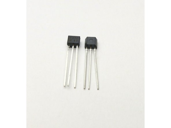
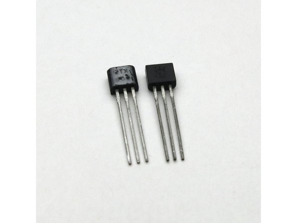
As shown in photo 1, the ZTX450 is just a bit bigger than the 2SK370.
-
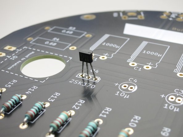
Note that the outline on the PCB is drawn in a way to look like the shape of the transistors, both of these are directional.
-
The slightly longer/bigger face of the transistor is called the flat, align it with the slightly longer side of the outline drawn on the PCB.
-
-
-
Slightly bend the leads and solder.
-
The transistors have 3 solder pads each, the capacitors have 2.
-
It is very important that the solder doesn't connect to other pads on the bottom... this is called a solder bridge and is bad.
-
The pads between the capacitor legs are a bit tight, be careful.
-
-
-
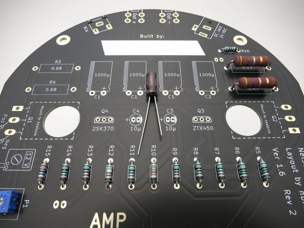
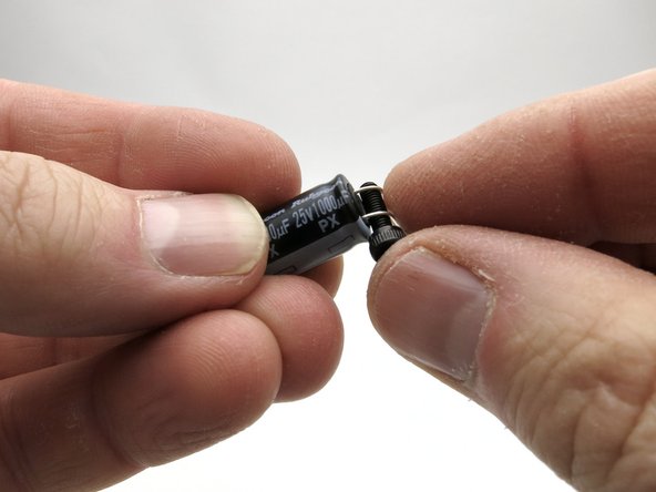
The leads of the 1000uF capacitors need to be bent down before installation.
-
Use one of the long screws as a bending guide.
-
Hold the capacitor as shown, with the negative marking towards you, and bend leads down 90deg.
-
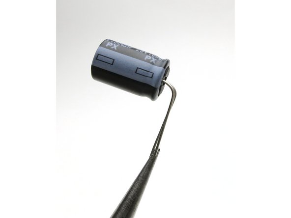
The caps should look like Photo 2 before installation.
-
Double-check your polarity, install and solder.
-
-
-
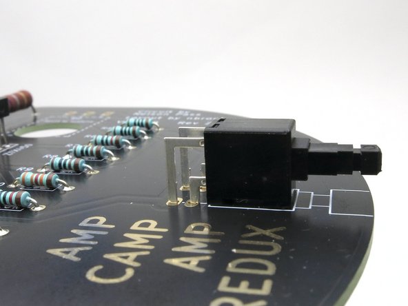
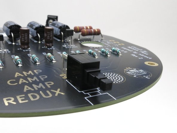
Make sure the switch is flat and square on the PCB before soldering.
-
The round cap (not shown) is press fit on the switch.
-
-
-
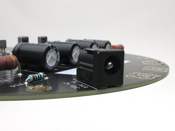
Make sure the DC power jack is flat and square on the PCB before soldering.
-
Photo 2 - As you can see, the solder tabs are a little short. It will still solder nicely with a bit of care.
-
-
-
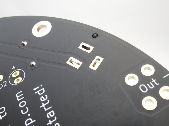
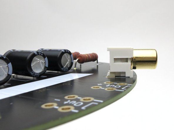
Like all the rest of the PCB mount jacks, ensure the RCA jack is flat and square to the PCB before soldering.
-
It may take a bit of effort to push it flat. That's ok, as flat and square to the PCB is the goal.
-
-
-
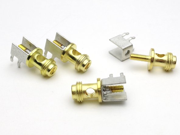
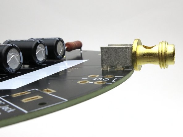
Solder the binding posts to the screw terminals before adding them to the PCB. This takes patience! Use a larger solder tip if you have one.
-
Align the holes in the binding post to be vertical when installed.
-
Some binding posts run out of threads when they're screwed all the way in. Adding the included split washer between the parts will help the threads stay engaged and hold alignment while soldering.
-
This will be easier if you remove the nut portion of the assembly, there will be less thermal mass to heat for effective soldering.
-
-
-
At this point the PCB should look like this.
-
Photos for reference.
-
-
-
Getting close to completely stuffing the PCB.
-
There are a couple things to stuff on the other side, these will point 'up' during normal operation.
-
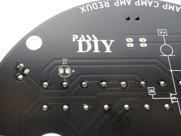
Please find the pads for the LEDs.
-
-
-
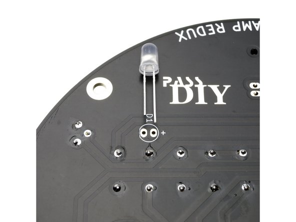
Insert the long leg of the LED into the + hole.
-
Flip the PCB and solder as normal.
-
Photo 3 for reference.
-
If you don’t like the color changing LEDs you may substitute solid color LEDs of your choice or leave them out entirely.
-
-
-
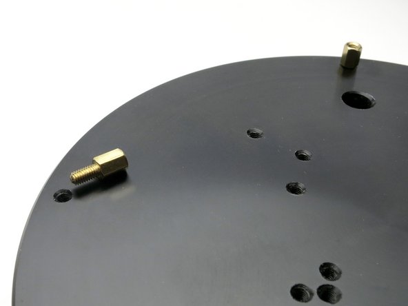
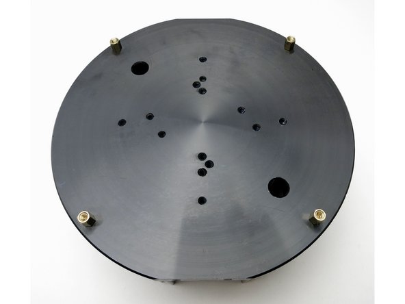
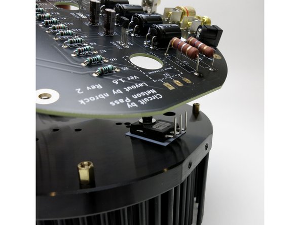
Screw the 4 brass standoffs into the outermost holes along the heatsink.
-
-
-
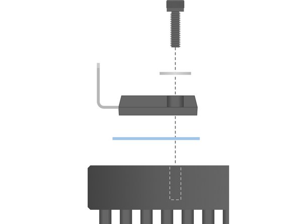
The transistor legs need to be bent up 90deg towards the plastic side of the body right at the point they narrow.
-
Bending can be done with pliers, but the leads naturally bend at the correct point even when done by hand.
-
-
-
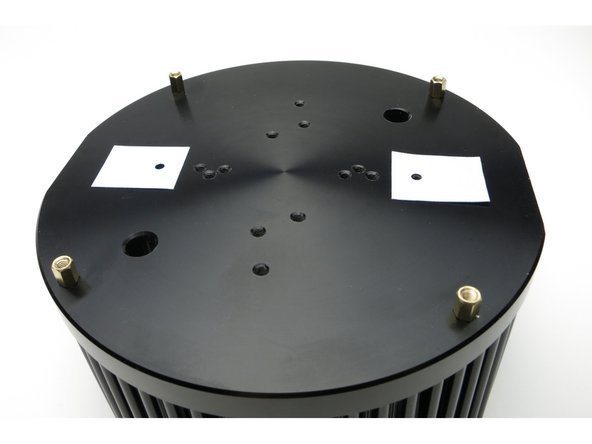
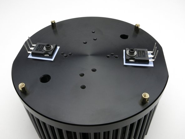
Photo 1 - insulator pads install here. Make sure they are clean and free of any metal crumbs or little solder blobs.
-
Photo 2 - attach the transistors to the heatsink with the screw and washer.
-
Do NOT tighten the screws beyond what will hold them in place loosely. They still need to move a little at this point.
-
Make sure the insulator pad is square with the transistor and 100% of the transistor is resting on the pad.
-
The heatsink and PCB assembly go together so the flat bits are aligned, it does not matter which of the large transistors is used as Q1 or Q2, they are identical and symmetrical at this point.
-
-
-
Before the PCB goes on, make sure;
-
...the (4) brass standoffs are inserted and secure,
-
...the big transistors have the blue insulators aligned nice and square under them and none of the transistor body is touching the metal itself,
-
...that the screw and washer holding the transistors are attached but not tight yet.
-
Make sure the 3 pins per transistor are in their holes.
-
-
-
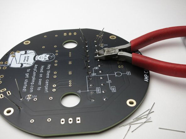
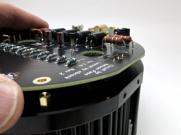
Make sure all the transistor legs are in the holes, then,
-
...gently wiggle the PCB and get the mounting holes over the brass standoffs,
-
...insert and attach the (4) black 'legs' into the brass standoffs and get everything squared up and snug.
-
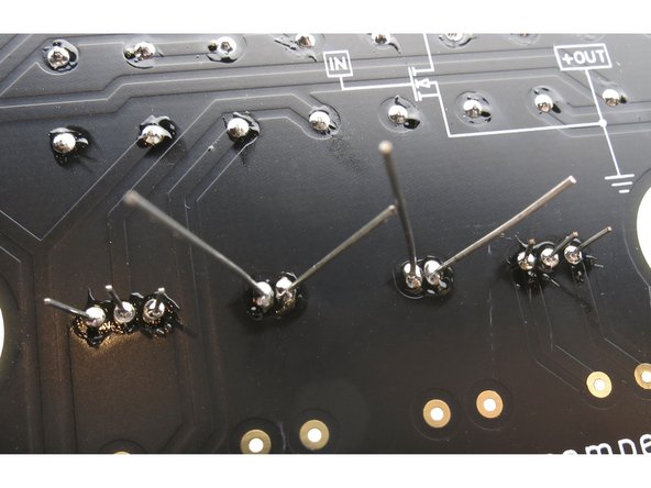
Photo 2 - Look under the PCB and make sure there are no uncut leads. The only things visible from the bottom should be the power transistors, the brass standoffs, and the LEDs.
-
-
-
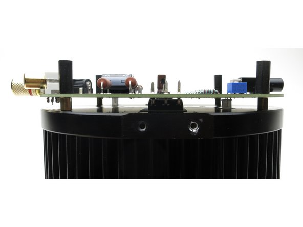
With the PCB attached with all four legs attached,
-
NOW you tighten the power transistor screws - firm, but not super tight. you want them to be attached fairly firmly, but don't break or bend anything,
-
and FINALLY, after the PCB is lined up, attached, and the transistors are tightened, you solder both power transistors to the PCB.
-
-
-
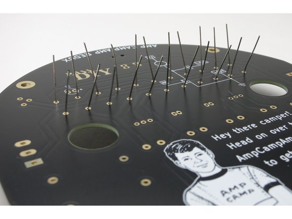
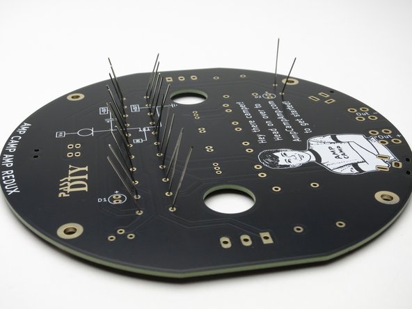
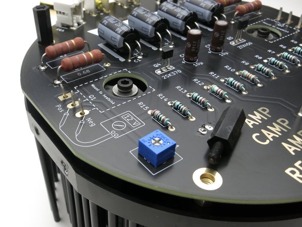
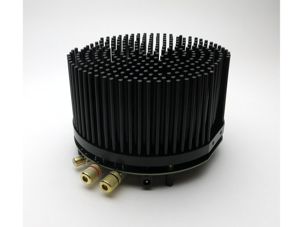
It looks like a mechanical hedgehog.
-
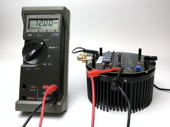
DC balance set to 12V.
-
-
-
A short video to show setting DC balance.
-
Be patient. Go slow. Enjoy the process.
-
-
-
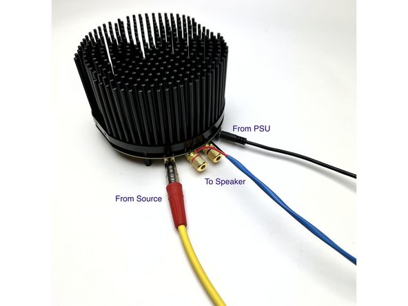
PSU attaches to the black barrel jack.
-
Input to the RCA jack.
-
Speaker wires attach to the binding posts.
-
-
-
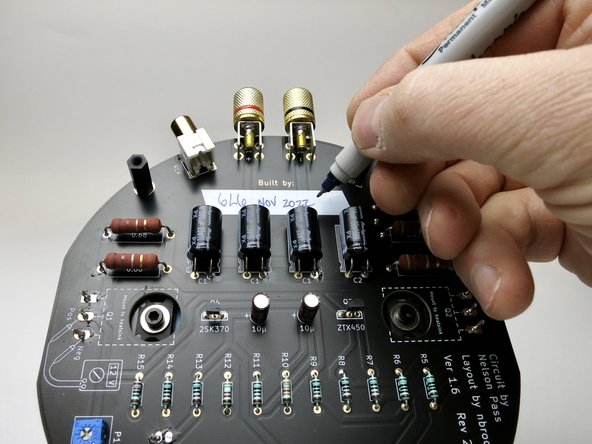
Make sure you sign your name to your new amplifiers when you complete them in the provided label space.
-
-
-
This works nicely. Be very gentle with it in this configuration, it's delicate and easy broken. But it sure is handy at times.
-


Cancel: I did not complete this guide.
3 other people completed this guide.