Introduction
This is an early guide for the Zenductor ACA being built at BAF 2026. It is not intended for use independently.
-
-
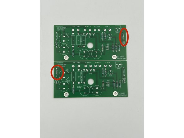
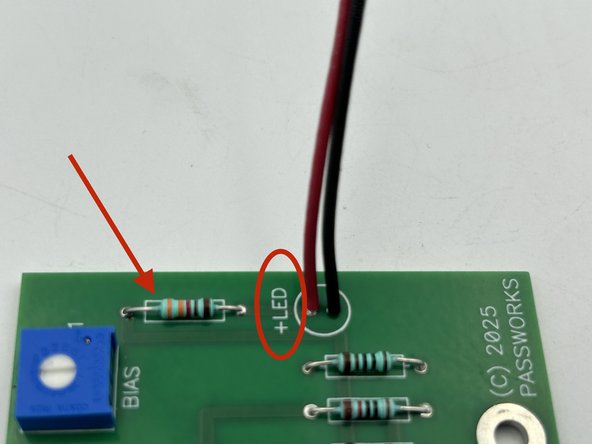
Make sure R11 (the LED resistors) are installed on opposite ends of each of the boards. This dictates the left and right channel board.
-
-
-
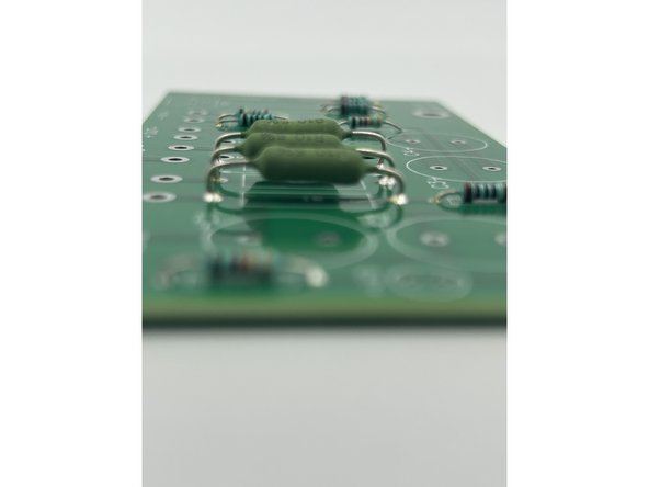
Use a coin (or anything a few mm tall) to aid in leaving a bit of space between the large resistors and the PCB.
-
-
-
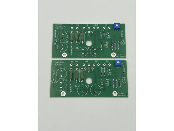
Install the pots.
-
-
-
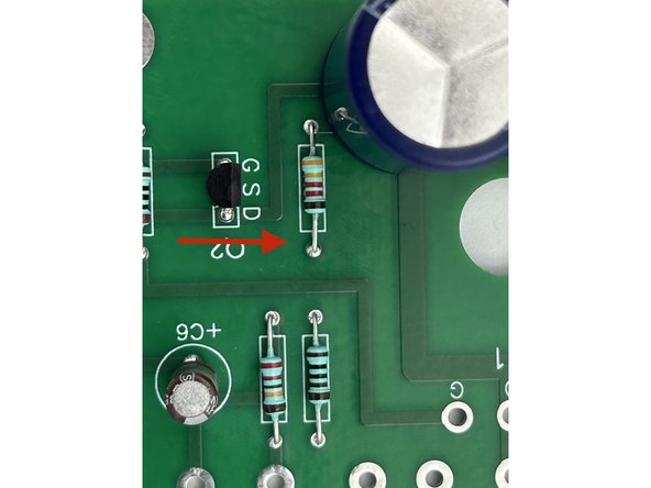
Pay careful attention to the orientation. J113 JFETs have a DSG (Pin 1, 2, 3) pinout. The 'face' is oriented to the center of the board.
-
-
-
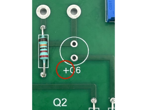
Pay attention to the cap orientation. The long leg is inserted closest to the pad with the (+) marking on the PCB.
-
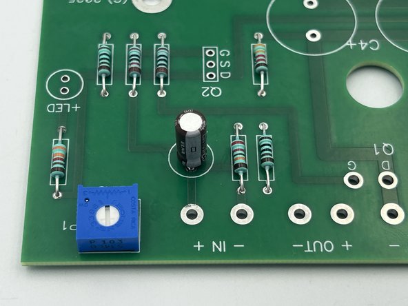
Install the small caps.
-
Photo 1 - Note the + next to the marker.
-
Photo 2 - Stripe facing away from the (+).
-
-
-
Pay attention to orientation similar to the small caps.
-
-
-
Do not twist
-
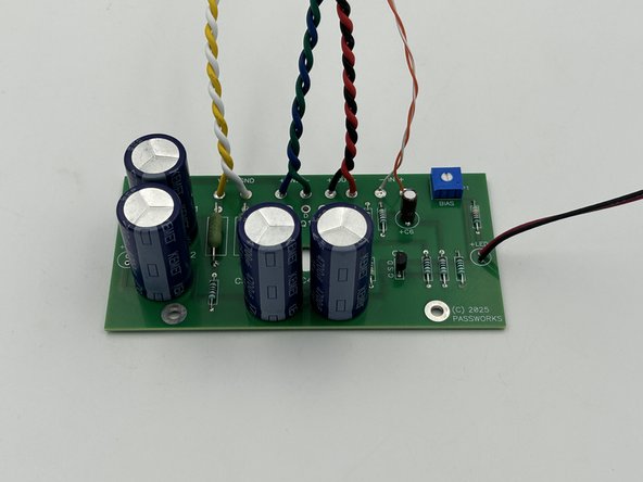
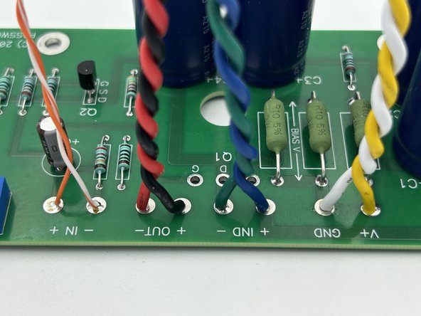
(V+) - 18 AWG Yellow - 18" (46cm)
-
(GND) - 18 AWG White - 18"
-
-
-
Note - The (Out -) is RED and the (Out +) is BLACK
-
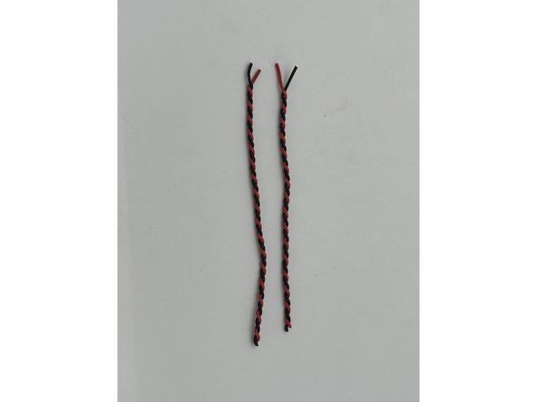
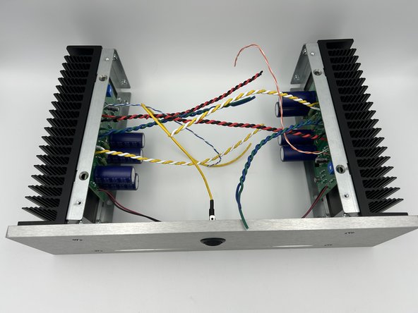
Twist 18" (46cm) of Red and Black 18AWG using the hand drill
-
-
-
Twist 14" (36cm) of the Blue and Green 18AWG wire using the hand drill.
-
-
-
Cut the LED leads to approximately 5" (13cm)
-
Note the polarity of the LED. Red is positive and corresponds to the (+) on the PCB.
-
Make sure to install the LEDs on the same ends of the boards as R11.
-
Solder the LED leads to the PCBs.
-
-
-
Cut about 2' (120cm) of CAT 5 cable. That is more than enough with plenty to spare in multiple colors.
-
Cut an 8" (20cm) section of the CAT 5 cable. Strip away the outer insulation. Separate the sets of twisted pairs.
-
Choose one set of twisted pair wires for the left channel and one for the right channel.
-
CAT 5 cable makes excellent input wiring. The individual strands of the CAT5 cable are 24AWG solid copper. Be careful when stripping the insulation. Do not nick the conductors. Do not over-handle.
-
Solder the solid-colored strand to (IN+).
-
Solder the white-striped strand to (IN-)
-
-
-
Use the Isopropyl alcohol and Kem-Wipes to clean the PCBs of residual flux.
-
Inspect each joint under magnification.
-
-
-
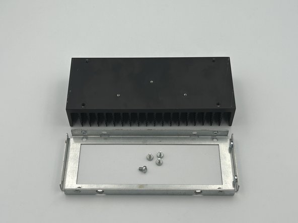
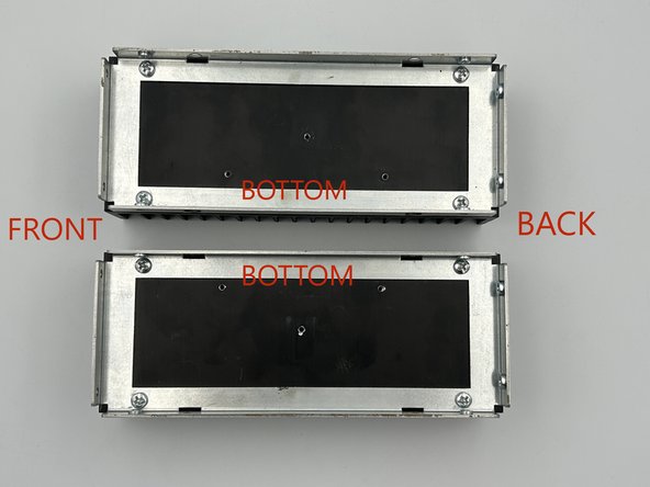
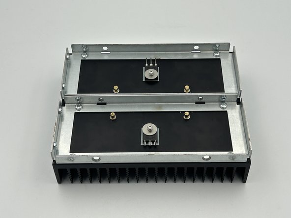
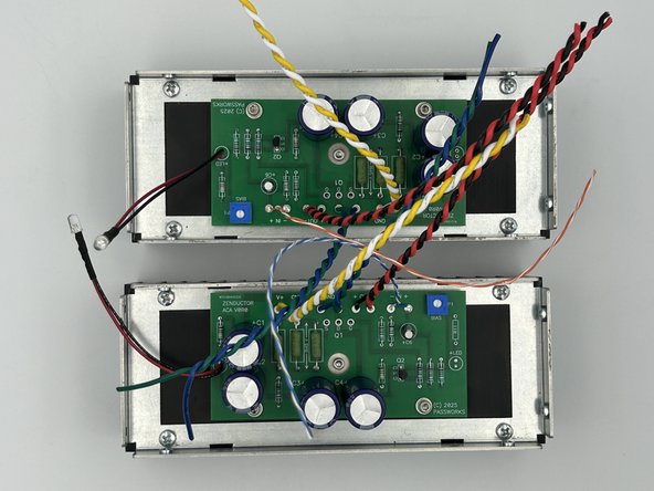
It is important to make mirror images of the heatsinks (see photo 2); one left and one right.
-
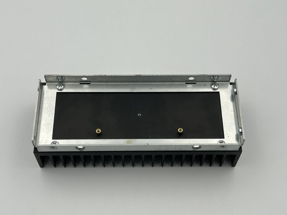
Mount the heatsink rails to the heatsinks using the M4 bolts included with the chassis.
-
Tip - To aid in having a square / aligned chassis, stand the short side (back) of the heatsink on a flat, even surface. Place the bracket with captured nut (these are used to mount the back panel) down against the surface. Ensure the back of the heatsink and the bracket are aligned and flat against the surface before tightening the bolts.
-
-
-
Install the standoffs with 3 x washers between the standoffs and the heatsinks.
-
-
-
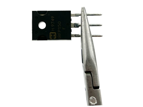
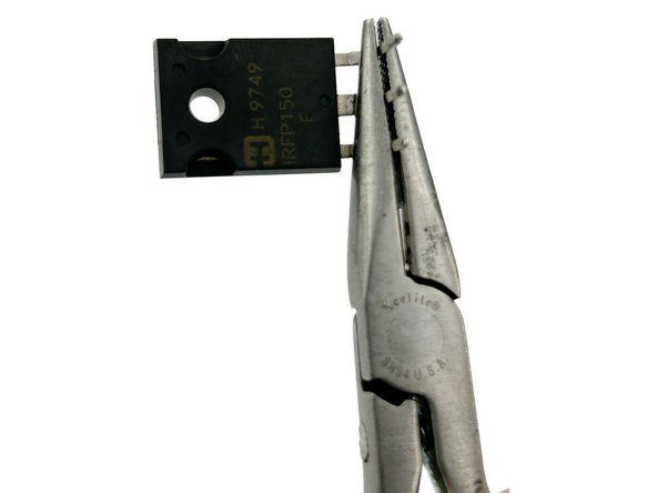
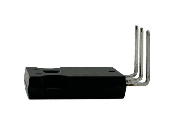
Bend the legs of the output devices to a 90 degree angle.
-
Bend the legs of the MOSFETs at the knee to a 90 degree angle.
-
-
-
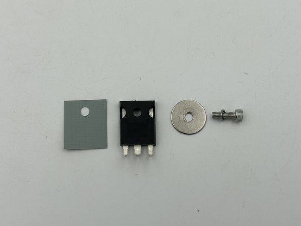
It is easiest to place all the components over the bolt and thread the bolt into the heatsink.
-
Align the MOSFET with the insulating pad.
-
Tighten the bolt just enough such that the when the MOSFET is moved, the insulating pad moves with it.
-
Rotate the legs away from the standoffs.
-
-
-
Gently slide the PCBs over the legs of the MOSFETs. Make sure that the LEDs are toward the front (away from the captured nuts on the heatsink rails).
-
Tip - Align the center hole in the PCB with the mounting bolt for the MOSFET.
-
Triple check that the boards are on the correct heatsink.
-
Mount the PCBs using M3 x 5mm bolts and flat washers.
-
Tighten the MOSFET mounting bolts to just beyond finger tight.
-
Quadruple check that the boards are oriented properly.
-
Solder the MOSFETs to the PCBs.
-
-
-
Using a DMM check to ensure that there is a very high resistance or open circuit between each MOSFET leg and a bolt on the chassis.
-
If there is continuity, seek assistance.
-
-
-
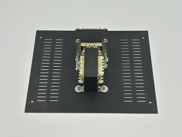
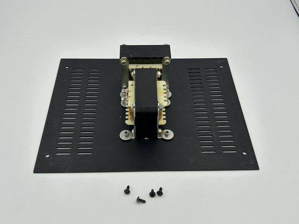
Mount the inductors to the bottom panel using black M3 x 10mm button head bolts, fender washers, and M3 lock nuts.
-
-
-
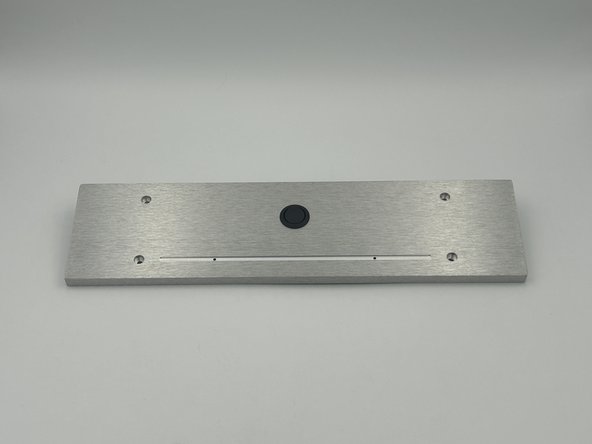
Install the Power Switch in the Front Panel
-
-
-
Cut about 6" (15cm) of CAT 5 cable. Remove all twisted pairs from the outer insulation.
-
Take the two twisted pairs using the same colors as were wired previously to IN(+) and IN(-) and separate the solid-colored strands.from the white-striped strands.
-
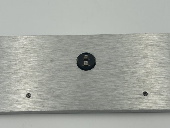
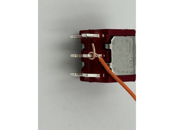
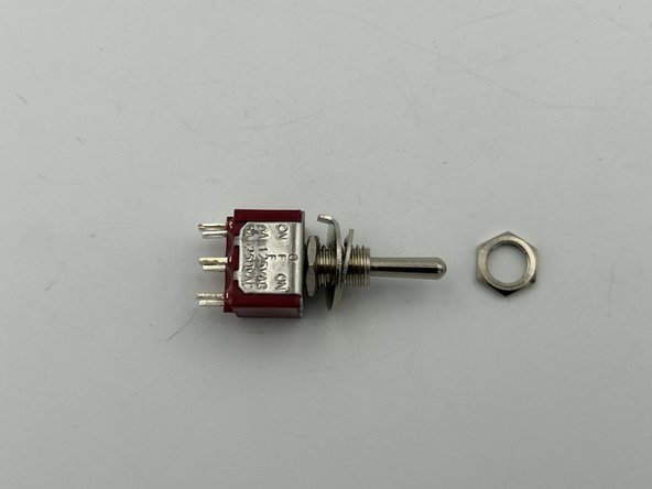
Tip - Make a tight bend in the wire around the hole in the switch pin. See Photo 1. It makes it much easier to solder. Trim the excess after soldering.
-
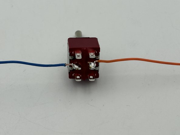
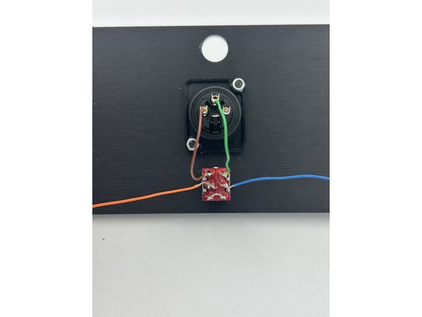
Solder one strand of each color to the middle positions on the switch. Orient them pointing to the 'sides'. It helps avoid an unceccary tight bend.
-
-
-
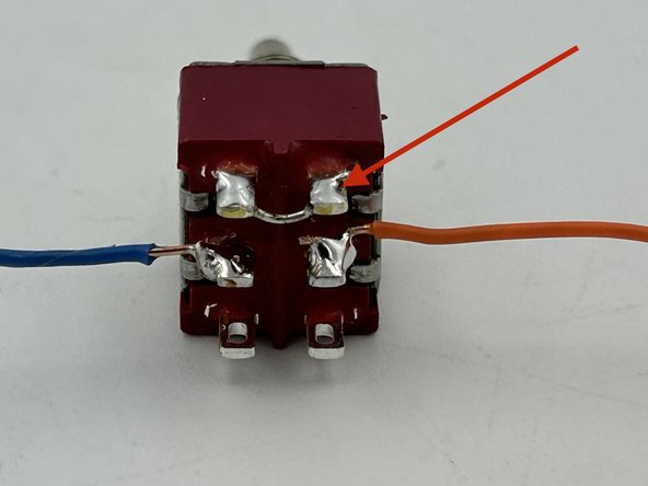
Use a small scrap of bare CAT 5 wire to connect the terminals on either end of the switch.
-
Tip - Insert the wire from the middle with the ends to the outer-side of the switch. This makes for easier soldering / trimming and helps to reduce the opportunity for unintended shorts between the terminals.
-
-
-
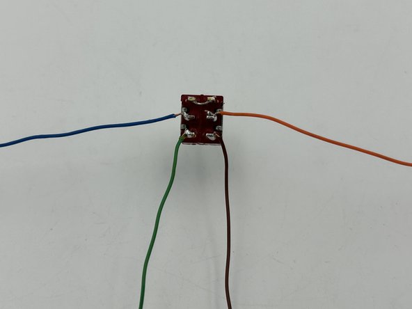
Separate the two other solid-colored strands from the CAT 5 twisted pairs.
-
Solder each wire to the two remaining switch terminals. Orient them pointing 'down'.
-
-
-
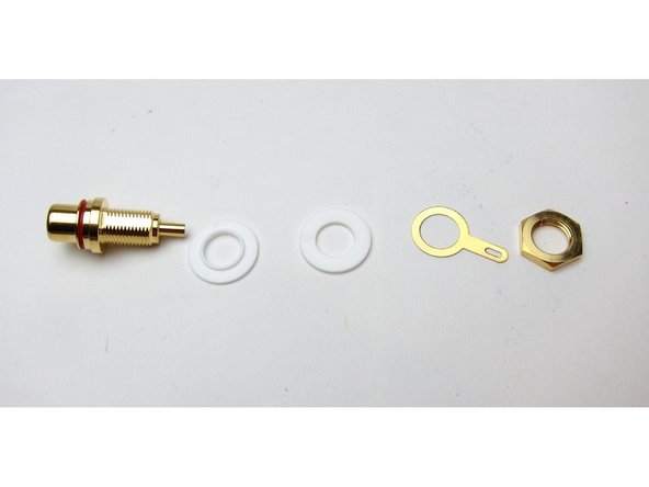
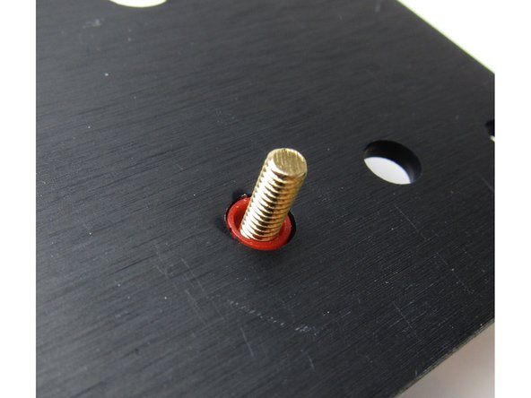
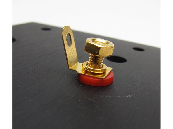
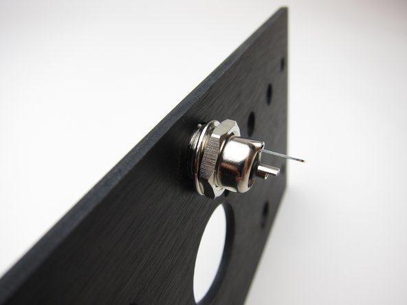
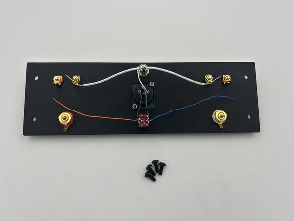
Tip - The RCA Jacks Ship with the components in a different order than implemented in this build. Pay attention to the GND tab in relation to the chassis and the plastic insulator. The GND tab should be separated from the chassis. See photo 1 for the proper order. Note - there is one additional hex nut to be installed.
-
Install the RCA jacks with the solder cup opening and the GND tab to the top of the panel.
-
-
-
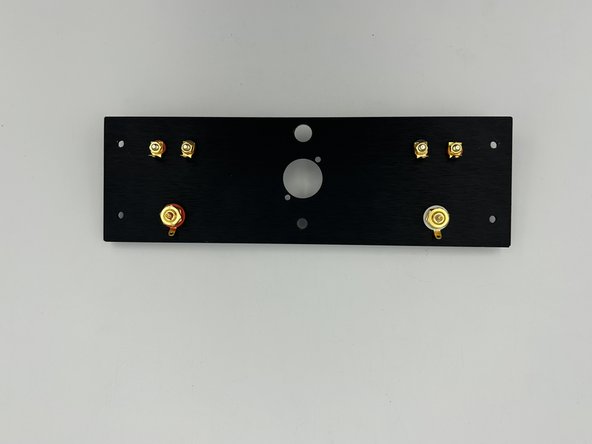
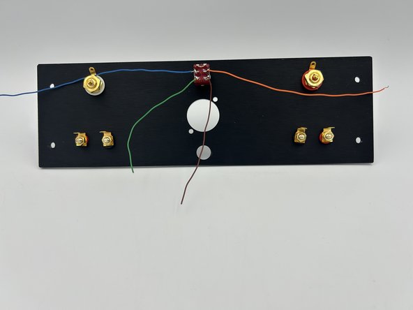
Tip - Make sure that the binding posts are installed with the red posts to the left and right edges of the back panel and the black binding posts in the middle. Photos are to demonstrate the order of assembly.
-
Install the binding posts with the tab pointing toward the middle of the chassis.
-
-
-
Hardware installation order: Nut => Washer (with notch facing the switch => Lock Washer => Back Panel => Nut
-
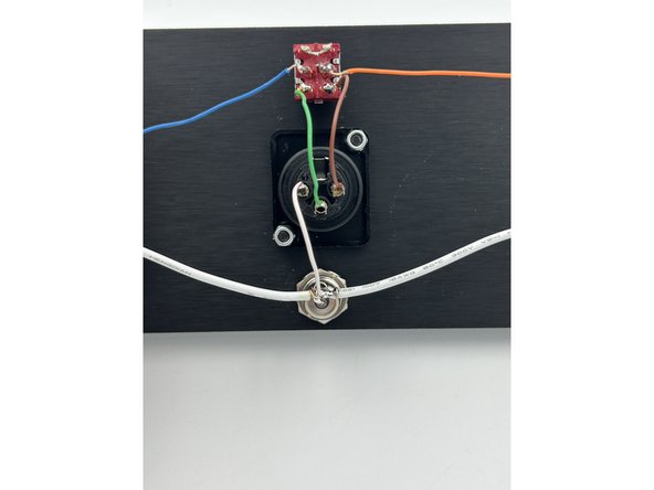
Install the switch onto the back panel with the wiring oriented as shown.
-
-
-
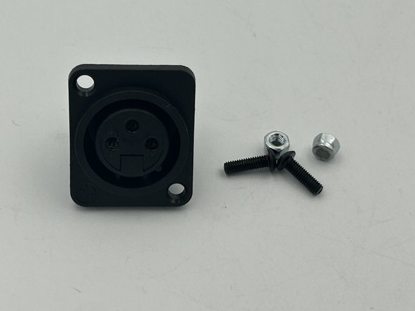
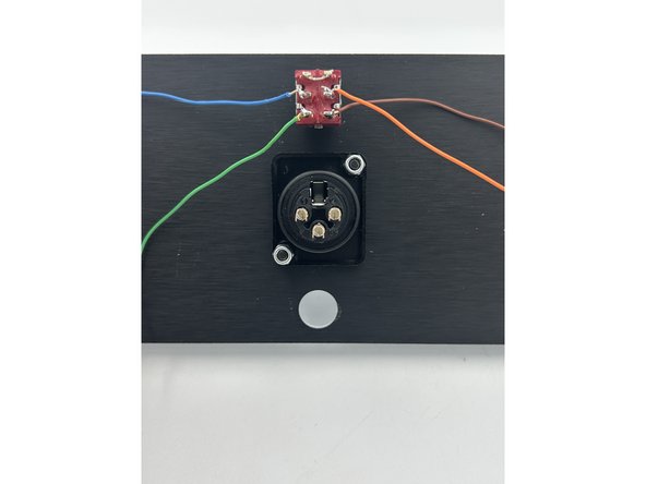
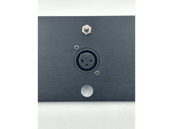
The XLR jack can be oriented two ways. It is recommended to install it in the orientation shown.
-
Install the XLR jack using M3 x 10 black button head bolts and M3 lock nuts.
-
-
-
Trim and solder the wiring from bottom positions on the switch to the XLR jack.
-
The wire from the switch on the side of the right input (B) is soldered to pin 2.
-
The wire from the switch on the side of the left input (A) is soldered to pin 3.
-
Solder a spare 6" piece of the white-striped CAT 5 conductor to pin 3 (not shown).
-
-
-
Install the DC Power Jack
-
-
-
The ground bus wire allows for easier attachment to the GND tab on the power inlet and acts similar to a star ground.
-
Cut an 8" (20cm) piece of white 18 AWG wire.
-
Using wire strippers, slit the insulation at the center of the wire. Separate the insulation at the center approximately 3/8" (1cm). This will be the ground bus wire.
-
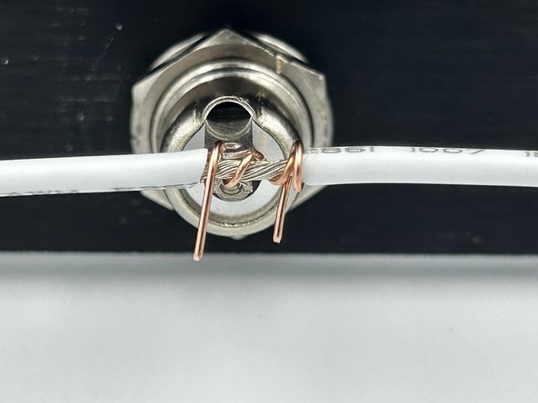
Strip the insulation from a small piece of spare CAT 5 conductor. Loop the wire through the hole in the ground tab of the power jack.
-
Wrap the CAT 5 wire around the exposed wire at the center of the ground bus wire holding the exposed wire in contact with the ground tab of the power jack.
-
Trim and strip the insulation from the white-striped wire attached to pin 1 of the XLR jack. Wrap the wire around the exposed portion of the ground bus wire.
-
Solder the ground bus wire into place.
-
-
-
Cut a 12" piece of Yellow, 18 AWG wire and a 3/8" piece of heat-shrink tubing.
-
Solder the wire to the center solder cup of the DC power jack and cover with heat-shrink.
-
-
-
Install the front panel to the heatsinks using your choice of black or stainless M4 x 12 bolts and M4 Lock Nuts. Do not fully tighten.
-
-
-
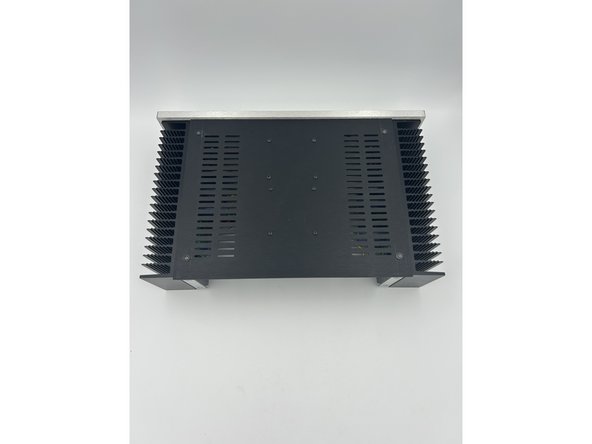
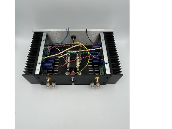
Note - the bottom panel must be oriented as shown in photo 2. It should sit flush against the front panel and have a slight (3mm) overhang beyond the back of the heatsinks.
-
Install the bottom panel using the black M3 cap head bolts included with the chassis. Take care to not break any of the wiring to the PCBs.
-
-
-
Install the 4, stick-on feet at each corner of the bottom panel.
-
-
-
Install the back panel using 4 black M4 cap-head bolts included with the chassis.
-
Tighten the front panel bolts
-
-
-
Three 18 AWG wires will be soldered to the tab on the black binding posts: White GND Bus, Black Speaker (+), and White GND.
-
Carefully trim and strip each wire. Leaving a little excess length is advised, just in case.
-
Tin the tips of each wire.
-
Install the wires into the binding post tab and solder into place.
-
-
-
Trim, tin, and solder the Red, Speaker (-) wire to the red binding post tab.
-
-
-
Cut a small piece of heat-shrink tubing. Slide it over the yellow, 18 AWG wire attached to the back panel power jack.
-
Trim, tin, and solder the yellow V+ wire to the bottom tab of the front panel power switch.
-
Trim each of the yellow V+ wires to the approximate length to the front panel switch. Leaving a little excess is recommended. Strip about 3/4" (2mm) of insulation from each wire. Carefully trim away about 1/4 of the strands from each. Twist the two wires together and test the fit in the power switch. Adjust as needed.
-
Tin and solder the two V+ wires to the power switch.
-
-
-
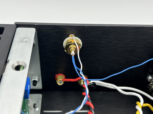
Solder the solid-color input wiring from the PCB (IN +) along with the solid color wire from the center row of the switch to the center post (solder cup) of the RCA jack.
-
Tip - Trim, twist and tin the solid-core CAT pair. Tin the solder up. Heat the solder cup and install the wires.
-
Solder the white-striped wire (IN-) from the PCB to the GND tab on the RCA jack.
-
-
-
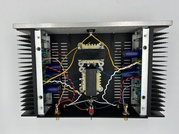
Note - The color of the wiring / position does not matter for the inductors.
-
Trim, tin, and solder the inductor wires to the inductors.
-
-
-
The target bias current for the amplifier is 2A5. This is measured across the source resistors (R2 and R3). There are two 0R1 source resistors in parallel => effectively 0R05. Using Ohm's law; the target voltage across R2 and R3 is 125mV.
-
Set a DMM to measure DC mV up to 200mV. Place the DMM probes across R2 or R3. Mini-Grabber probes are a big asset.
-
Ensure the power switch is down / off. Plug in the power supply.
-
Turn both pots fully counter clockwise
-
Turn on the power. The DMM should read 0V. Slowly turn the pot CW until there is approximately 100mV across R2 and R3.
-
Allow the amplifier to come to temperature. Make small adjustments until the voltage is 125mV +/- 10mV and is stable for 20 minutes.
-
-
-
Grab a pair of test speakers and a source and listen for any noticeable distortion or other issues.
-
Attached Documents
