Introduction
What Are We Building?
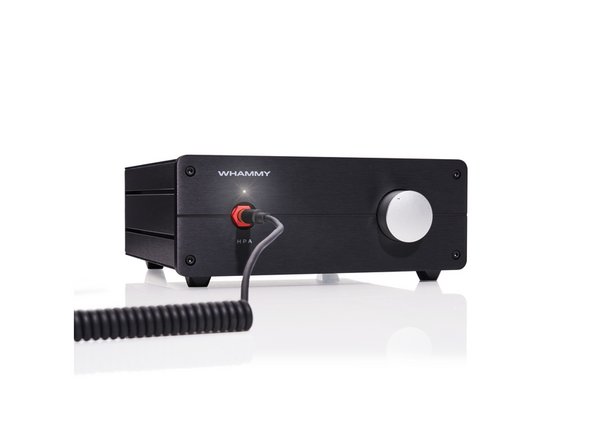
This guide covers the assembly of the:
Wayne's
Headphone
Amplifier
Must
Make
Yourself
Here is a video of Wayne talking about the WHAMMY at BAF 2017: Wayne Colburn at BAF '17
100s of DIYers have built the WHAMMY. It is many people's favorite headamp for good reason.
|
What Is Covered In The Guide?
This is a build 'guide'. It is not an instruction manual. The purpose is to assist in learning and guide DIYers with helpful information. Builders should not expect every detail to be covered.
|
It is not the only information needed to complete the project. Some additional links are included as guidance. It is critical to understand that the guide is intended to be a representation of how to complete the project. It is not the only way to complete the project. As an example, many builders choose to "roll op-amps", which can be a lot of fun. Builders that are unsure may want to begin with the assembly outlined in this guide, ensure that they have a working project, and then decide if they'd like to make any modifications. It's DIY, choose your own adventure and have fun.
|
The project is considered moderately difficult. The guide is not intended to instruct someone through their first project. This guide is best suited to someone with an interest in audio electronics that has built one or two audio projects and needs a few helpful hints. However, many people, including this guide's author, successfully assembled the WHAMMY (with some assistance) as their first DIY project. Whether you are a first-time builder or have built 100s of projects, it is highly recommended to review this guide fully before beginning the build.
|
Builders should have a basic knowledge of electronics and should be proficient in through-hole PCB soldering. Although there are many helpful tips throughout the guide, before attempting to build this project, the builder should be confident in their ability to:
|
- SAFELY work with electronics powered with mains voltage,
- follow a schematic and identify the proper placement of parts from the schematic onto the PCB,
- understand basic measurements to identify parts correctly, and
- properly solder a variety of through-hole components.
|
What Else Do You Need?
If you chose a full kit, then everything you need to assemble a working amplifier is included in your kit minus the tools. However, we've suggested a few helpful tools, just in case.
|
Most importantly, if you have questions, please seek help in the forum.
Enjoy!!!
-
-
A black bullet is an instruction or valuable information.
-
Everything in this guide is important, but here's how you'll know something is REALLY important.
-
A green bullet is the mark to do something.
-
Warnings will be noted with a warning symbol and bold, red, underlined text. Pay Attention!
-
Tips and tricks and helpful reminders will be noted with an information bullet.
-
Photo / Image captions and information will be noted with the Photo/Image Icon.
-
-
-
Click on the image to enlarge and read the warnings carefully.
-
Construction of this project requires working with potentially deadly mains voltage. In constructing this kit and following this guide, you agree to assume liability for any injury or damage resulting from exposing you or others to these voltages.
-
This guide demonstrates using the full kit from diyAudiostore.com which includes a proper enclosure. The builder must have or acquire an enclosure properly isolating mains voltage from unintentional contact and have the knowledge to validate proper safety conditions have been met.
-
-
-
If you do not possess the skills or knowledge necessary to safely complete this project, STOP! Seek assistance.
-
Never assume that shock hazards have been alleviated, even when the unit is not powered. Capacitors can store a lot of energy.
-
Use clip leads for your DMM. Attach and remove the leads with the circuit de-energized. DO NOT connect leads with the unit under power. Disconnect the mains power whenever it is not strictly required for testing.
-
Wear proper Personal Protective Equipment (PPE) including rubber-soled shoes and safety glasses. Work on a concrete or hardwood floor. DO NOT work around water or other liquids.
-
-
-
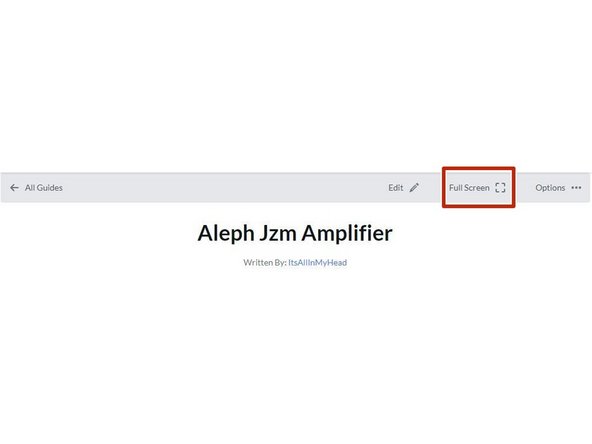
Your first "real" black bullet. You may notice that you have the option to view in "Full Screen". I like it either way, but I prefer full screen. This web platform works well with tablets too. I've tested it with various monitors of various aspect ratios and tablets. Choose what looks best to you. The printed .pdf format is nice too.
-
Image 1 - If you don't know how to get to "Full screen", take note of the box around "Full screen" at the top of the guide above the header / title. That's where you click to move to Full Screen.
-
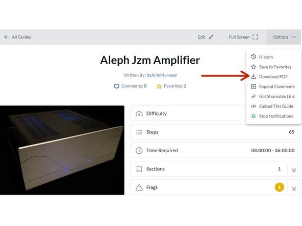
Image 2 - If you don't know how to print the document. Note that you can download this guide as a .pdf and print it.
-
In all the on-line views, if there are multiple images and/or photos within a step, mouse-over or tap/click as appropriate to make which ever one you'd like the primary image (the biggest one).
-
Mousing over / tapping on the primary image will change the cursor to a magnifying glass. Clicking / double tapping will open a new tab or enlarge and center the image on your screen.
-
In full-screen mode, the keyboard right and left arrows or clicking the arrows in the upper right will advance or reverse one step.
-
Your first "real" green bullet. Choose if you want to view in full screen or standard (if you haven't already) and/or print a copy of the guide.
-
Get started. Move on to step 5.
-
-
-
All mistakes are preventable, and this guide moves slowly through each step.
-
The most common issues with builds are mis-stuffed parts and poor solder joints.
-
Symptoms from mis-stuffed parts typically manifest quickly. For this build, pay particular attention to the voltage regulators and the output MOSFETs. The impact from an improper part placement can be benign, or you could release the "magic smoke".
-
The impact of poor soldering varies. A short/bridge that will impact your build is unlikely, but can be catastrophic. More commonly, the issues are partial coverage or a cold joint. Symptoms may not manifest until you least expect them, and they may be intermittent. Inspect each and every joint under magnification. You'll be glad you did.
-
DMM issues can lead to frustration.
-
Check the batteries. When in doubt, replace the batteries.
-
Make sure your probes are reading "0 Ohms" resistance probe to probe or the probes are appropriately compensated.
-
Make sure your probes are connected properly. For this guide, the polarity of the voltage being read isn't critical, but it's best practice to always observe and report polarity. If you are troubleshooting, it is likely the polarity will matter.
-
-
-
The notation of voltages requiring a decimal place may have a "V" in place of the decimal. 24V5 is 24.5 Volts or 24,5 Volts.
-
The notation of resistance requiring a decimal place may have a "R" in place of the decimal. 0R5 is 0.5 Ohms or 0,5 Ohms.
-
The notation of Amperage requiring a decimal place may have an "A" in place of the decimal. 1A1 is 1.1 or 1,1 Amperes.
-
-
-
The most common action you'll take throughout the guide is to "install" your parts AKA stuff the PCB. Parts installation includes:
-
Ensuring you have the correct parts to match the PCB silkscreen / schematic.
-
Ensuring the leads are bent to the proper pitch (if applicable).
-
Soldering the parts into place.
-
Cutting the leads to the proper length*
-
It is also acceptable to clip the leads to the correct length prior to soldering. There are compelling reasons to do it either way. If you are unsure, watch a few videos, read a few articles, and do some test soldering of your own to see what works best for you. If you choose to clip prior to soldering, use the correct tool.
-
Cleaning and inspecting the joint. It is strongly recommended to use magnification and good lighting to inspect each and every joint.
-
-
-
This guide does not cover how to solder / install through hole parts. There are a variety of great ways to install a part and achieve a proper solder joint, but there are common themes throughout. Below are a few links. See what works best for you. Neither diyAudio nor the author have any affiliation with any of the companies or persons linked.
-
-
-
-
-
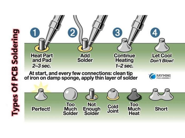
Image 1 - A basic soldering sequence and examples of both good and poor joints. Taken from the Rayming PCB & Assembly Guide linked above.
-
The key variables to soldering are the type of solder chosen, the tip used, and the tip temperature. These all vary widely between users and are inter-related. If you are new to electronics, the best solution is practice. Scrap electronics and inexpensive parts are a wonderful way to learn.
-
Leaving the iron tip on the joint for longer than around 5 seconds is not a substitute for too small an iron tip or too low a temperature. If you need to reflow a joint, or if the solder isn't flowing, flux is your friend.
-
-
-
The builder must ensure all terminations are done properly for safe and trouble-free operation.
-
It is often discussed whether to solder and/or crimp or whether spade-type connections are worthy of a "good" build. In the author's opinion, a properly-crimped connection using high quality terminations and a proper crimper is an excellent choice. Adding solder to a crimp is some people's compromise, but it will never "fix" an improper crimp.
-
The advantage is that many crimped terminations allow flexibility.
-
The disadvantage is that a proper crimp is only achievable when using a proper tool, and many people don't have a proper crimper for each type of termination.
-
Adding solder to connectors / terminations intended for crimping only may lead to wire fatigue and a 'brittle' connection.
-
The video linked does an excellent job of demonstrating various crimps. You are strongly encouraged to watch it. Link to Excellent Crimping Video. Note - Neither the author nor DIYAudio have any affiliation with the video's creator.
-
-
-
Plan your build. Read this guide a few times before you even take the first part out of the bag.
-
Go slowly. You're not getting paid to do 100 boards a day. This should be relaxing and fun. A lot of errors can be traced back to lack of attention and rushing.
-
The ONLY parts within reach should be for the step you are working on at the moment. Many parts look very similar.
-
Move the boards and your body around to give yourself the best angle to solder each part. Get close to your work and use magnification. A well-lit workspace is important. You don't stand a chance if you can't see.
-
Before moving to the next part, triple check your work. Hopefully you won't make any errors, but it is much easier to remove one part than many to fix an error. Using the included documents and following a basic sequence will assist with error-free construction.
-
Take plenty of breaks and stop at any point confusion or frustration sets in. There are a few recommended stopping points throughout the guide, but stop any time you mentally or physically need to recharge.
-
Try to keep distractions to a minimum.
-
Neatness counts!!! Take pride in your work. You'll be happy you did.
-
-
-
Print a copies of each the documents found at the end of this guide or in the Documents Tab if you are viewing in Full-Screen Mode. You'll need to go back to the Introduction (full-screen mode) or scroll to the end of the guide to find the documents / documents tab.
-
Tidy up your workspace. Keep in mind that you'll be working with a very hot soldering iron, and it can be easy to misplace parts. A few recomemndations:
-
No other parts for any other projects should be within arm's reach.
-
The floor and the area around the workspace should be clean, just in case a part escapes.
-
-
-
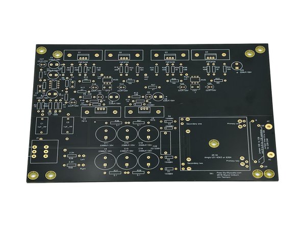
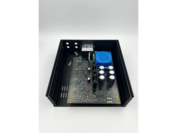
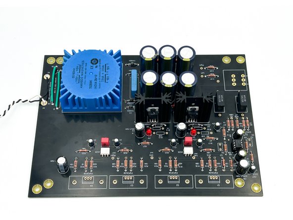
Look over your boards and get familiar with the parts placement.
-
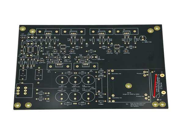
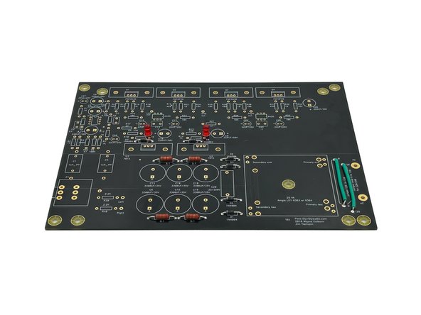
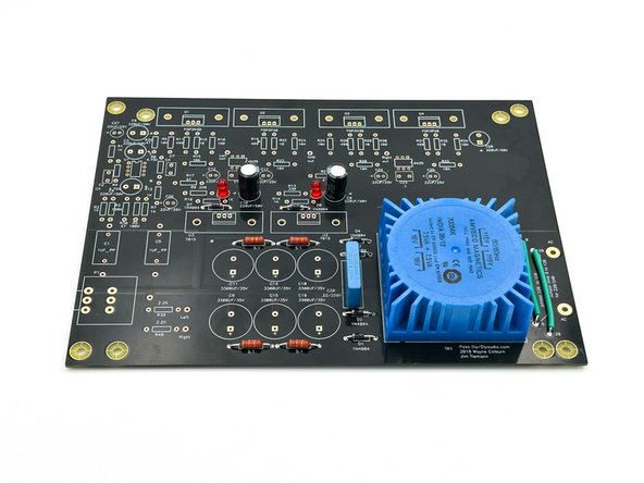
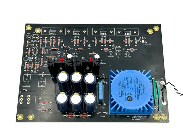
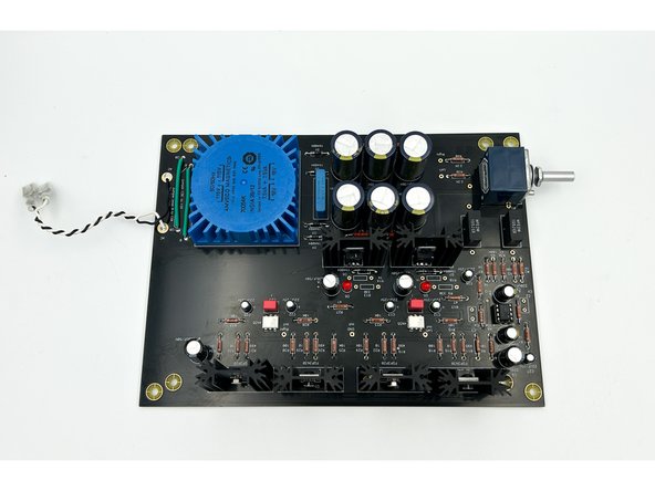
Image 1 - Front view of the PCB, sometimes referred to as the component side.
-
You will not stuff every component. The PCBs include options for various power supply configurations. This guide covers the most popular configuration.
-
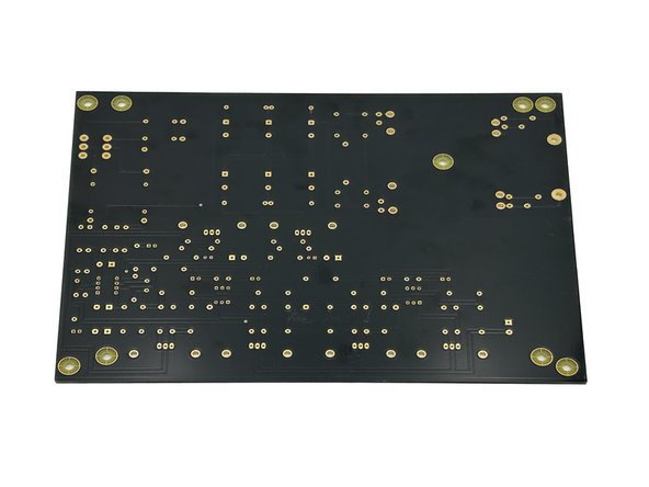
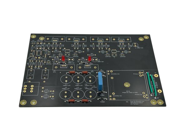
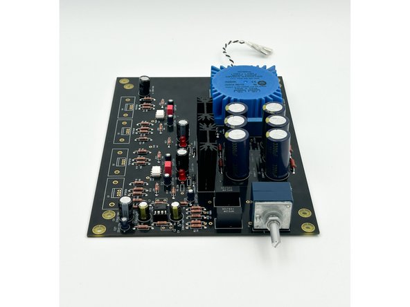
Image 2 - Back view of the PCB, sometimes referred to as the solder side. You will not install any components on the back of the board for a typical build. However, there are one or two notes for more advanced builders that may want to install components on the back of the board. This will not be demonstrated in the guide.
-
-
-
Generally, we prefer the flow of installing the shortest parts to the tallest. However, for this build, since it is a single PCB, the recommended sequence deviates slightly. The PSU segment will be assembled and tested first. Once the PSU is verified, the rest of the components can be installed.
-
Each section of the stuffing and inspection checklist can be done together. It is not important to do each part within a section in order. As an example, it is not recommended to install the small resistors in numerical sequence. Install them in groups of the same value. That makes assembly faster and results in fewer errors.
-
The examples in Steps 14-16 are from an Aleph Jzm build, but the exact same principles apply to the WHAMMY. The steps illustrate the use of the documents to ensure the board is stuffed properly and has the highest likelihood of working properly on the first attempt. Builders are free to use their own methods and/or adapt what's been provided.
-
-
-
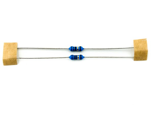
It is not necessary to install all the parts in exact order. Within a parts group, my preference is to:
-
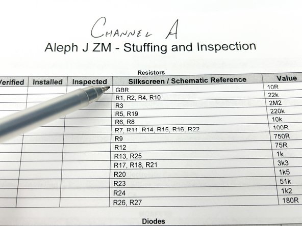
Photo 1 - Remove one set of parts from the parts bag. In this case a pair of resistors. For the WHAMMY, many of the parts will not be on cut-tape. Builders may choose to measure, pre-sort, and label all the parts prior to installation.
-
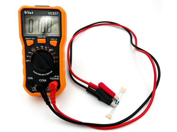
Photo 2 - Measure / validate the part. In this case, measure the resistor with a DMM.
-
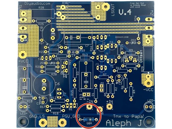
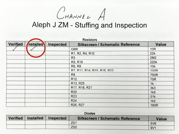
Photo 3 - Validate which part corresponds to the part in-hand using the stuffing and inspection list.
-
-
-
(Continued)
-
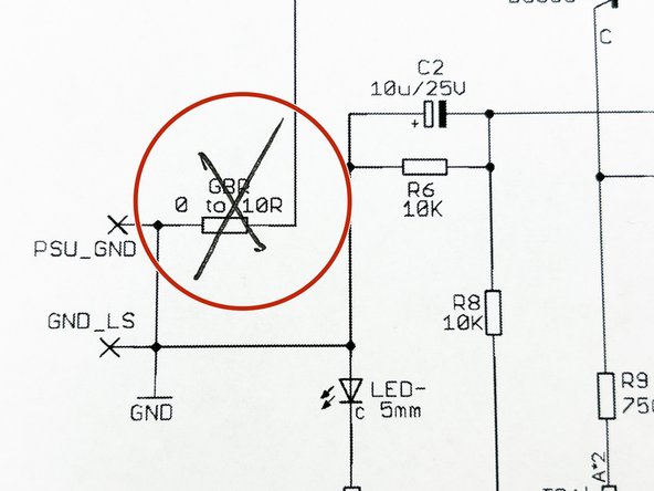
Photo 4 - Validate that the part notation and value match the schematic and cross the part(s) off the schematic.
-
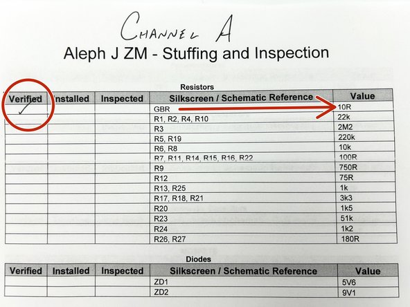
Photo 5 - Note the part(s) value was verified against the schematic.
-
-
-
(Continued)
-
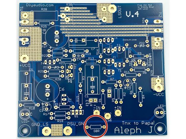
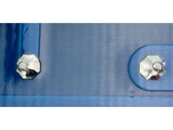
Photo 6 - Validate the part's placement on the board.
-
Photo 7 - Install the Part
-
-
-
(Continued)
-
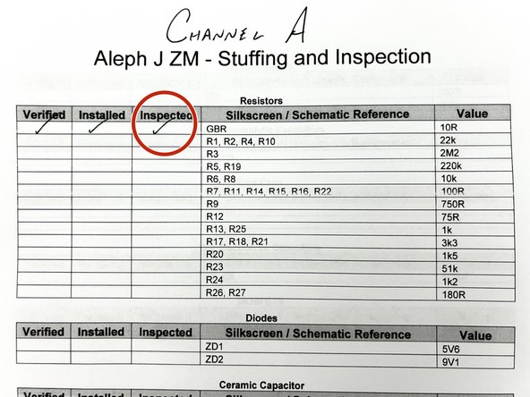
Photo 9 - Note that the part was installed.
-
Photo 10 - Inspect the joints. Clean as needed.
-
Photo 11 - Once everything looks great, note that the part(s) have been inspected.
-
-
-
Open the bags of parts, verify them against your packing list and get to know what they look like.
-
Place all of your parts carefully in a bowl or somewhere they will not get lost, knocked onto the floor, accidentally spread around your workbench, or mixed in with other parts not associated with this project.
-
Many people like to separate their parts by type. For this project, it's not necessary, but choose whatever method works best for you. It's fairly simple to keep all the parts together and select only what is required for a particular step.
-
-
-
Tidy up your workspace. Keep in mind that you'll be working with a very hot soldering iron, and it can be easy to misplace parts.
-
Clean both sides of the board with isopropyl alcohol or your favorite PCB cleaner. A dust and oil free board helps the solder to flow nicely. Plus, they're very pretty. Yes, that's real gold.
-
Ambitious DIYers may trace the board with a DMM in continuity mode against the schematic. Don't worry, the boards match the schematics, but give it a try.
-
-
-
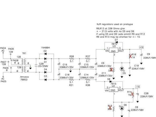
If you haven't already, print the PSU schematic. The .pdf is included in the documents section.
-
Image 1 - For this build, you will not install, R9, R10, R13, or R14
-
-
-
Ensure you have your PSU Schematic and your stuffing and inspection checklist.
-
It is important to test the power supply before installing other critical components. It will help prevent a number of potential problems later in the build.
-
This guide demonstrates the most popular option using a red LED as a voltage reference. It is the quietest option, and it functions beautifully. Advanced DIYers can explore other options separate from this guide. If you wish to explore other options, visit the WHAMMY build and discussion thread. Link to Discussion Thread
-
REMEMBER - NOT ALL COMPONENTS WILL BE INSTALLED.
-
-
-
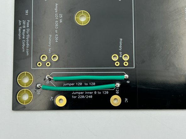
The PCB is configured for both 110/115 VAC and 220/230VAC mains voltages. Selecting the mains voltage is as simple as installing a jumper wire or two.
-
For 110/115VAC - Cut two pieces (about 2.5" / 6.5cm) of the black or white hookup wire (it does not matter what color) and install the jumpers as shown in photo 1. Note - The green wire included in the kits is a little large.
-
For 220/230VAC - Cut a single piece (about 3" / 7.5cm) of the black or white hookup wire (it does not matter what color) and install the jumper as shown in photo 2. Note, the green wire included in the kits is a little large.
-
Photo 1 - Install jumpers as shown for 110/120VAC (Once again - the green wire in the kits will likely be a little too large in diameter).
-
Photo 2- Install jumper as shown for 220/230VAC
-
-
-
Remember to measure the resistance for every part before installation and follow the validation / installation / inspection process.
-
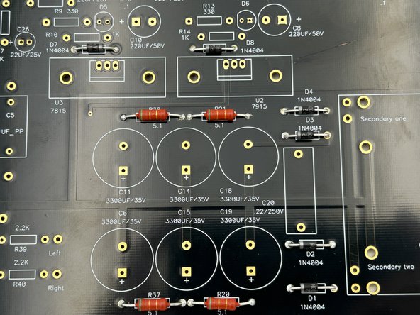
It is helpful to use a lead forming tool. The pitch for the large resistors is 3/4"(19mm). The pitch for the diodes is 1/2"(13mm)
-
Install R20, R21, R37, R38 and D1, D2, D3, D4, D7, D8. Pay attention to the orientation of D7.
-
Photo 1 - Your board should look something like this. Ignore the boneheaded scratch, please.
-
-
-
Photo 1 - The Anode (Positive, Long Leg) of the LEDs is installed with the square pad.
-
Install D5, and D6
-
Photo2 - LEDs installed.
-
-
-
The film cap, C20, does not have a polarity. It can be installed in either direction.
-
Install C20
-
Photo 1 - C20 Installed
-
-
-
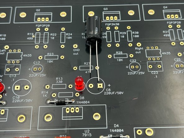
Your kit contains two types of 200uF capacitors. One type is rated for 50V and one type is rated for 25V. Ensure you install the 50V capacitors. The voltage rating is marked on the package. They are physically larger than the 25V capacitors, and you can match the quantity on your parts list.
-
Verify the orientation of the electrolytic capacitors! The negative side a.k.a. the cathode is indicated with a band. The cathode lead is the shorter of the two leads. The positive side a.k.a. the anode is the longer of the two leads. The anode aligns with the square pad. A (+) is also indicated on the silkscreen.
-
Photo 1 - The longer of the two leads aligns with the square pad
-
Install C8 and C10
-
-
-
The transformer will only install into the PCB in one orientation. If you need to bend the pins slightly, do so gently. Do not try to force the transformer into place.
-
Install the transformer
-
Photo 1 - Transformer Installed
-
-
-
Verify the orientation of the electrolytic capacitors! The negative side a.k.a. the cathode is indicated with a band. The cathode lead is the shorter of the two leads. The positive side a.k.a. the anode is the longer of the two leads. The anode aligns with the square pad. A (+) is also indicated on the silkscreen.
-
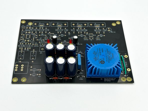
Install the large capacitors, C6, C11, C14, C15, C18, and C19
-
Photo 1 - Capacitors Installed
-
-
-
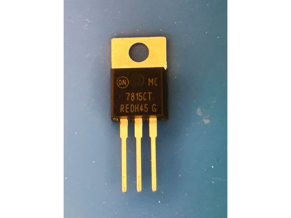
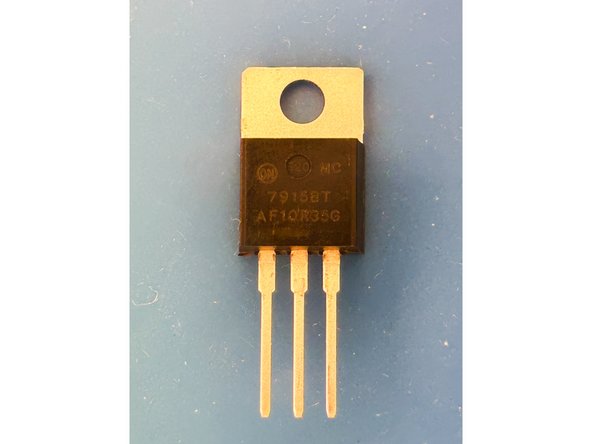
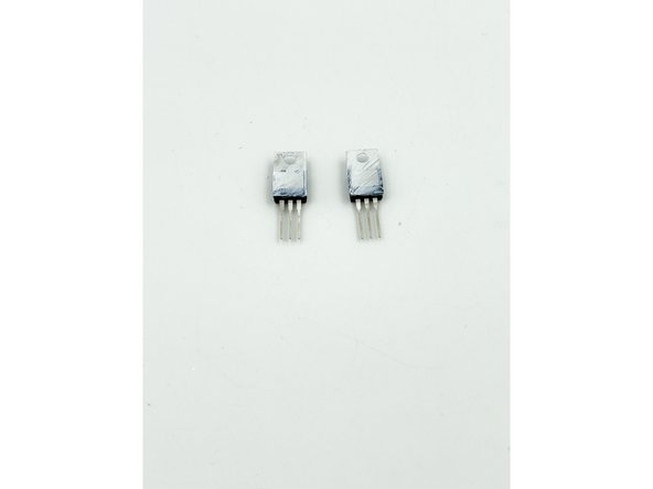
Ensure that you identify the voltage regulators and separate them. Use magnification if needed and double check the case markings.
-
Photo 1 - 7815 Regulator
-
Photo 2 - 7915 Regulator
-
-
-
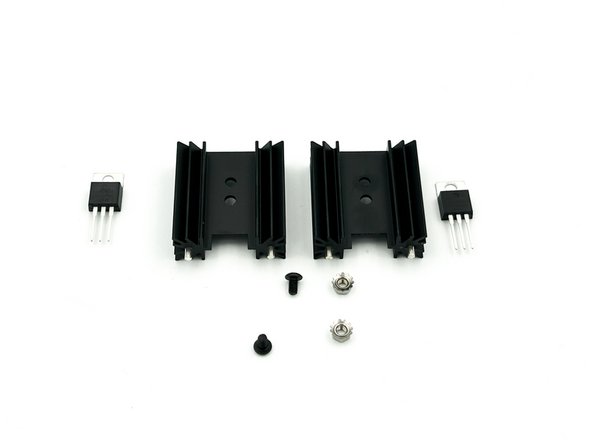
2X Heatsinks, 2X 5mm Cap Head Screws, 2X K-Nuts, and the thermal paste are required for this step.
-
Photo 1 - Heatsinks, 2X 5mm Cap Head Screws, 2X K-Nuts
-
Spread a small amount of thermal paste onto the back of each regulator. A little goes a long way. Place the regulators back-to-back and wiggle them a little to spread the paste evenly.
-
Photo 2 -Thermal paste applied
-
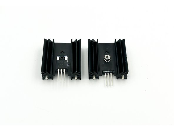
Install each regulator onto a heatsink using the screws and nuts. Install them regulators into the lower holes. Do not fully tighten. Ensure that the legs of the regulators align with the heatsink pins.
-
Photo 3 - Regulators loosely installed onto heatsinks (front and back).
-
-
-
Identify one regulator assembly and slide it into the position marked U2 for the 7915 or U3 for the 7815. Both 7915/7815 and U2/U3 are marked clearly on the silkscreen. Double check it!
-
Solder the pins of the heatsink only to the PCB to hold the regulator assembly in place. If you have a large tip and/or a soldering station with a variable temperature control; now is the time to put a little heat to it. If you do not, just be patient. You can hold the iron to the heatsinks for quite some time without damaging anything.
-
Tighten the bolt / nut to securely hold the regulator to the heatsink. There is no need to overtighten. Just a little over 'finger-tight' is perfect.
-
Repeat the steps above for the other regulator assembly.
-
Triple check that the regulators are in the correct locations. Solder the legs of the regulators in place.
-
The legs of the regulator are soldered in place last for two reasons. 1 - To allow the builder to check, double-check, and triple-check this important operation a number of times before soldering. 2 - Tightening the assembly before soldering allows the part to be in place fully before soldering, thus reducing stress on the joint.
-
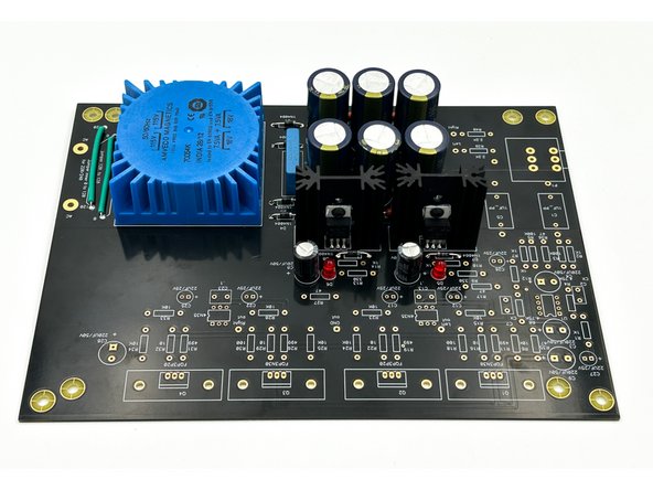
Photo 1 - Regulators Installed
-
-
-
Knowledgeable, experienced, and extremely careful? Foolish, brave, and hasty? Some or all of these terms may apply to a builder that chooses to test their mains AC power supply on an open bench. This guide demonstrates testing the PSU with the PCB temporarily mounted in the chassis with a connection to mains earth in place.
-
It is important for both safety and performance that all the chassis panels are 'bonded'. Each panel must be electrically connected to the other throughout the chassis and most importantly to mains earth. There are various methods to accomplish this, but one of the simplest is to remove the anodization in various places.
-
Builders that are too aggressive with removing the anodization may have visible bare spots, particularly where the front panel meets the side panels. It is strongly advised to do a test fit with each panel prior to removing the anodization and remove the anodization slowly. A black "Sharpie" can help correct any issues, but it's best to go slowly.
-
Please review the warnings in Step #2 and Step #3. STOP and request assistance if you are unsure.
-
While not required, it is recommended that you use a variable transformer for initial testing of the PSU.
-
-
-
It is the builder's responsibility to ensure ALL mains connections and wiring are secure.
-
In this guide, all terminations were both crimped and soldered to the wire. A proper crimp is more than sufficient, but adding solder may add a level of security in the event the crimp is not perfect.
-
The female spade connectors included in the kit are specifically designed for the PEMs included in the kit, are high quality, and are very secure. Some builders still may choose to solder the wire or connector directly to the PEM. It should be noted that the PEM provided in the kits is not intended for a soldered connection.
-
In order to get a proper crimp, the proper jaws are essential. Crimpers with interchangeable jaws are available from a number of on-line suppliers at reasonable prices. One example is provided in the Tools section of the guide.
-
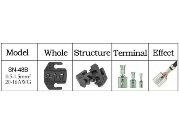
Photo 1 - Example of crimping jaws for female spade terminations.
-
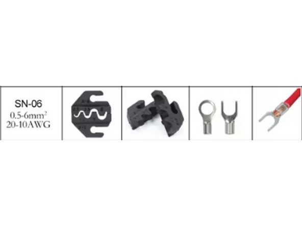
Photo 2 - Example of crimping jaws for bare ring terminals. It should be noted that the crimping jaws for insulated ring terminals are not the same.
-
Please review the crimping video linked in step 9 if there is any uncertainty. The kits include an extra spade terminal for practice or if there is an error.
-
-
-
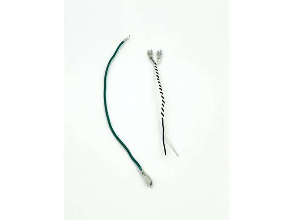
Cut approximately 6" of the green wire. Crimp and/or solder one 6.3mm female spade connector to one end. Slide the spade insulator onto the wire and over the spade. Crimp and/or solder one ring terminal to the other end. Note - The insulation was removed from the ring terminal allowing it to be crimped and soldered.
-
Cut approximately 6.5" of the white and black wires. Crimp one 6.3mm female spade connector to one end of each wire. Slide the spade insulators onto the wire and over the spades. Twist the black and white wires together leaving approximately 1/2" on the spade end and approximately 1" on the bare end.
-
In the USA, black is typically used to designate the live wire carrying the current to the load. White is typically used to designate the neutral wire providing the return path. The neutral wire will typically be connected to mains earth within the building.
-
Photo 1 - Two wire assemblies; Mains Earth connection and AC Live and Neutral.
-
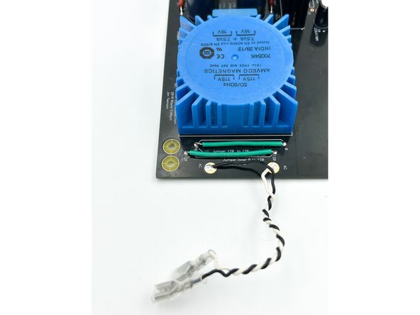
Solder the white and black wires to PCB at the positions marked "AC". Live (black) should connect to the lead winding of the primary, which is the AC pad towards the middle of the PCB. Neutral (white) should connect to the trailing lead, the AC pad closer to the corner.
-
Photo 2 - AC wiring attached to PCB
-
Note - This is a test to see if you were paying attention. The white and black leads are reversed in the photo. The written instructions are correct.
-
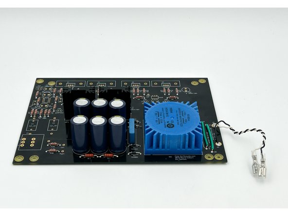
Photo 3 - PCB with completed PSU section.
-
-
-
Removing too much anodization will result in visible bare spots. A test fit is strongly recommended prior to removing anodization to ensure you do not remove too much. Some builders have suggested painter's tape to protect certain areas of the panels. Go slowly.
-
Using your favorite method (a rotary tool works nicely as does a few scrapes with a razor blade) expose some bare metal by removing the anodization from the side panels in a few places where they will meet the top, bottom, front and back panels.
-
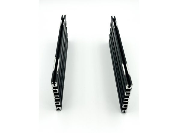
Photo 1 - Side panels with some anodization removed. It's a bit overkill in this example. The 'bottom' and 'front' of the side panels (not visible) also have the anodization removed similarly.
-
Ensure you identify the "interior / exterior" surfaces of the top and bottom panels. The exterior surface has the countersunk holes for fastening to the side panels.
-
Remove some of the anodization on the INTERIOR surface of the top and bottom panels where they will meet the side panels along with an area around the ground mounting hole on the bottom panel.
-
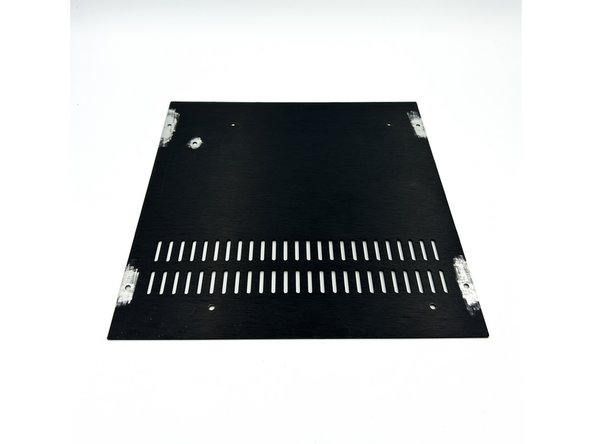
Photo 2 - Bottom panel with some anodization removed.
-
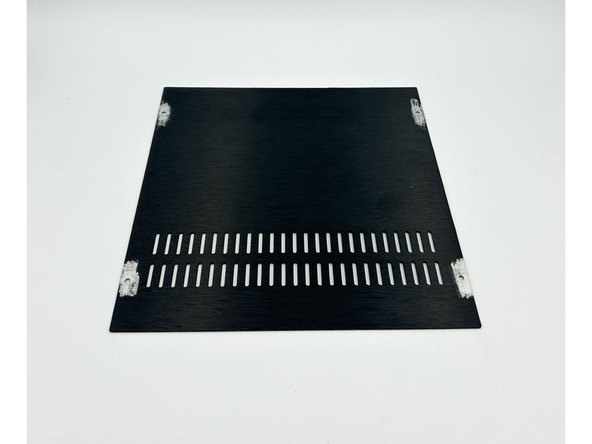
Photo 3 - Top Panel with some anodization removed.
-
-
-
Most people like to toggle the switch 'Up' to turn the unit on. This orientation is demonstrated. Make sure you check the PEM orientation before removing the anodization. As noted below, it can't hurt to remove it on both sides of the PEM.
-
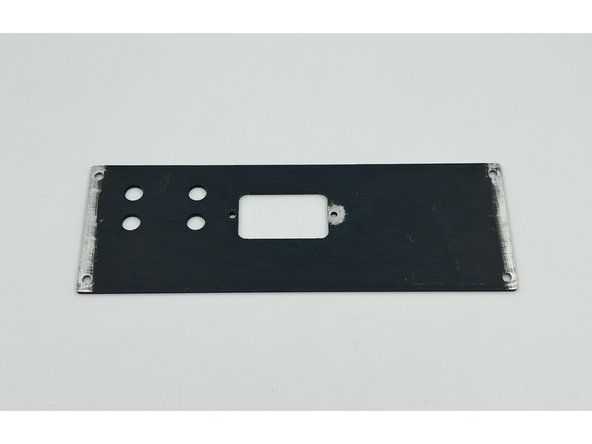
Remove some of the anodization on the interior surface of the back panel where it will meet the side panels along with an area around the mounting hole for the PEM closest to the earth lug. If in doubt, remove the anodization around both holes. It is critical to remove the anodization where Protective Earth connects to the chassis.
-
Photo 1 - Interior of Back Panel
-
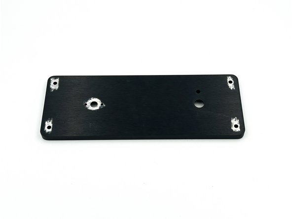
Remove some of the anodization on the interior of the front panel where it makes contact with the volume pot and the side panels.
-
Photo 2 - Interior of Front Panel
-
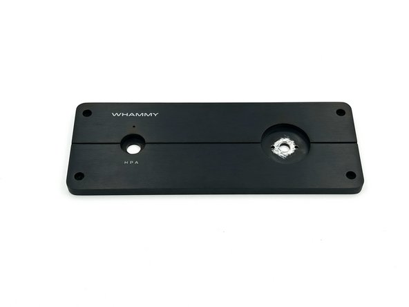
Remove some of the anodization on the exterior of the front panel where it makes contact with the volume pot.
-
Photo 3 - Exterior of Front Panel
-
-
-
Slide two of the M3 nuts included with the chassis into each of the side rails.
-
Fasten the bottom panel to the side rails using the black flat head screws included with your chassis. Leave them just slightly loose. Note - the side with two slots typically faces the interior of the chassis, but choose whatever you like aesthetically.
-
Set the side panels upright on a flat surface and allow the bottom panel to slide down leaving a slight gap at the 'top'. Tighten the screws to the bottom panel. The bottom, top, left, right, front, and back of the chassis are now established.
-
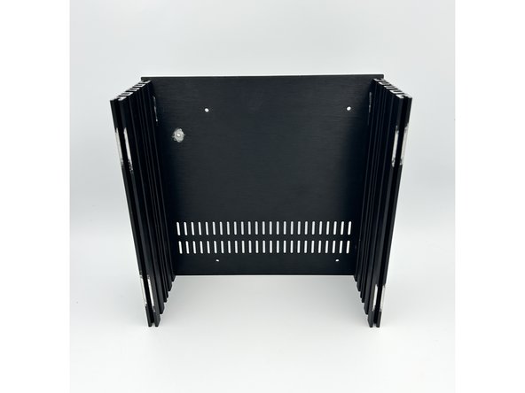
Photo 1 - The M3 screws slide into the top notch on each side panel. Note, this photo was taken before the anodization was removed.
-
Photo 2 - Side panels attached to the bottom panel. Placing the assembly upright on a flat surface before tightening the screws ensures the proper gap at the back of the chassis.
-
Photo 3 - Notice the gap at the top. This is the back of the chassis.
-
-
-
Using the larger black, flat head screws included with the chassis, securely fasten the back panel to the side panels.
-
Most people like to toggle the switch 'Up' to turn the unit on. Make sure your orientation is the way you like it. Slide the PEM through the back panel from the exterior. Using a black 10mm flat head screw and a Keps nut, loosely secure the PEM to the back panel on the side furthest away from the mains earth tab on the PEM.
-
Using a black 10mm flat head screw and a Keps nut, secure the ring termination of the green wire assembly and the PEM to the back panel. Ensure that the ring termination is making clean contact with the bare metal exposed on the rear panel.
-
Tighten both screws / nuts securely. Slide the 6.3mm female blade connector onto the PEM mains earth tab. The connection should be tight. If it is not, stop and seek assistance.
-
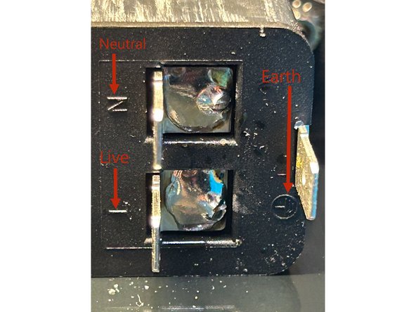
Photo 1 - Note the markings on the PEM indicating the connections to mains power.
-
Photo 2 - Initial "test bed".
-
-
-
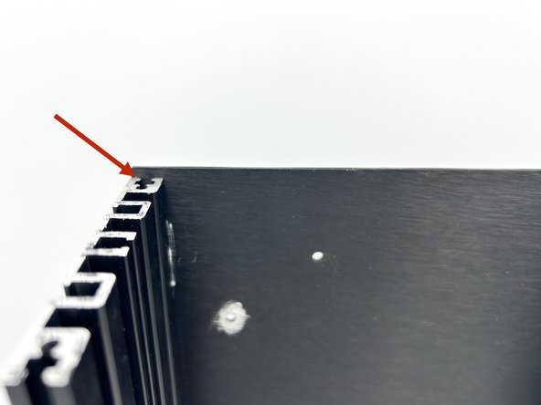
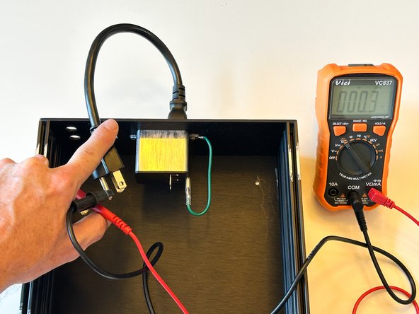
With your DMM set to resistance / continuity. Measure the resistance from your mains earth to the bare metal on each panel. If it is more than a fraction of an Ohm, STOP!
-
Read the previous step again and validate that each panel has less than one Ohm resistance to the mains earth connection.
-
Photo 1 - Note the very low resistance from mains earth to the left side panel as one example. It is critical to ensure a low resistance from mains earth to all panels.
-
-
-
Now is a fantastic time to inspect each and every solder joint again. Triple check each electrolytic cap, the diodes (D7), and ensure that the regulators are installed in the correct locations.
-
Using M3 nuts, mount two standoffs to the rear of of the PCB in the holes closest to center. Using black, 5mm cap screws, mount two standoffs in the front two holes of the bottom panel of the chassis.
-
Slide the PCB onto the bottom panel and the front standoffs. The PCB should slide under the PEM.
-
Slide both 6.3mm female spades from the black and white AC connection wires onto the PEM spades marked L and N. Black is live and white is neutral. The connections should be tight. If they are not, stop and seek assistance.
-
Photo 1 - PCB temporarily mounted in the chassis. Note - The mains earth configuration was altered after this photo was taken.
-
-
-
The PEM provided with the kits (Schurter DD12.9111.1111) switches both live and neutral. The fuse drawer provided with the kits fuses the live connection. Builders are responsible for understanding all applicable regulations that apply to their area.
-
The fuse provided with the kit is a Schurter 5x20mm, 125mA, slow-blow / time delay. It will function for both 110/115 and 220/230 VAC. Builders with 220/230 VAC mains may choose to purchase a 63mA fuse separately if they would like to use the lowest recommended amperage rating.
-
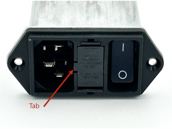
Place the cartridge fuse into the fuse drawer as shown in photo 1.
-
Install the fuse drawer and fuse into the PEM. The tab indicates the direction. Do not force it. Just slide it in until it clicks. Note - PEM is not installed in the chassis for ease of demonstration.
-
Photo 1 - Fuse and Fuse Drawer
-
Photo 2 - Proper Installation of Fuse Drawer. Note the position of the notch.
-
-
-
You will be working with mains power. Take precautions. Precautions include but are not limited to ensuring you do not place your hands, any conductive materials, or your DMM probes near the PEM or the AC input side of the PCB near the transformer. Ensure the workspace is free of clutter. Protective eyewear should be worn.
-
If you have a variable transformer, it is a good time to use it.
-
Connect a standard C14 power cord to the PEM. Make sure the plug is not connected to mains or your variable transformer yet.
-
Toggle the PEM power switch into the On position.
-
Prepare - If you hear any pops, smell any smoke, see any sparks, or sense any other type of failure; immediately unplug the unit from mains. Troubleshoot / seek assistance as necessary before proceeding
-
While standing at least the length of your power cord away from the unit, and ensuring that no body parts are above the PCB, plug the power cord into AC Mains or your variable transformer (set to the lowest output voltage).
-
If you are using a variable transformer, slowly increase the output voltage until you reach your mains output voltage.
-
-
-
Check the PCB. Both LEDs should be lit.
-
If both LEDs are not lit, STOP! Troubleshoot as required. Seek assistance if necessary. Do not proceed.
-
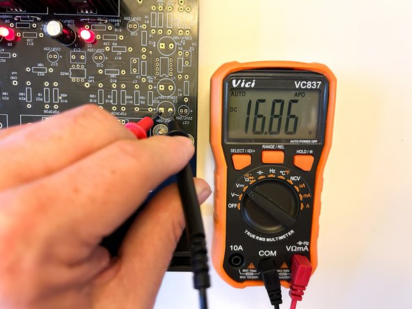
It is critical over the next two steps that you do not touch the tips of your DMM probes together while they are in contact with the PCB. It is highly recommended to use two hands. Do not use the technique shown in the photos. A slipped probe is no fun!
-
With a DMM set for DCV, carefully place the black probe of your DMM on the circular pad for C9. Carefully place the red probe on the square pad for C9. You should read approximately +17VDC. The polarity is important.
-
Photo 1 - Notice the probe positions. Acceptable voltage at +16.86VDC
-
-
-
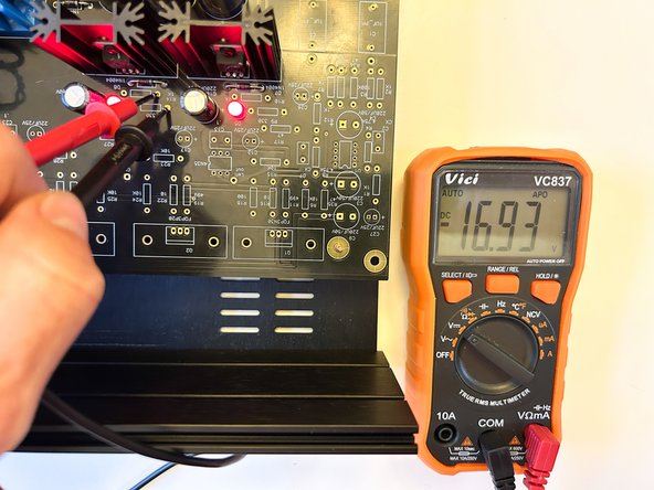
With a DMM set for DCV, carefully place the black probe on the pad for R13 closest to C10. Carefully place the red probe on the pad for R14 closest to C10. It should read approximately -17VDC. The polarity is important.
-
Photo 1 - Photo 1 - Notice the probe positions. Acceptable voltage at -16.93VDC
-
If for any reason you did not get correct voltage readings, STOP! Troubleshoot and/or ask for assistance before proceeding.
-
Turn off the unit and disconnect the power cord.
-
Disconnect the live and neutral wires from the PEM and remove the PCB from the chassis. Remove the standoffs from the PCB and from the chassis.
-
-
-
Congratulations! You have now completed the PSU section for your WHAMMY.
-
Do a little happy dance. We insist.
-
-
-
If you have not already, print the schematic for the audio circuit. .pdf files are included in the documents section of the guide.
-
Image 1 - PSU schematic. There are still parts in the PSU circuit to install.
-
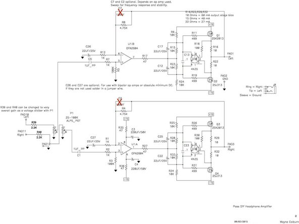
Image 2 - Audio schematic. Note, for a standard build using the OpAmp provided, C2 and C7 are not necessary.
-
For those that choose to experiment with different OpAmps, it is wise to determine appropriate values for C2 and C7. Other modifications to the circuit may also be necessary. Proceed with knowledge and caution. It is strongly recommended to build the circuit as designed before doing any modifications
-
-
-
Remember to measure the resistance for every part before installation and follow the validation / installation / inspection process.
-
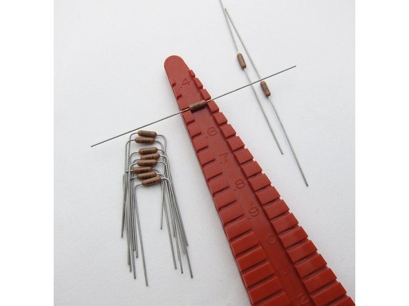
It is helpful to use a lead forming tool. The pitch for the small resistors is 1/2"(13mm).
-
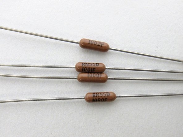
Photo 1 - The code for Dale resistors uses a 3-digit + multiplier at values greater than 100ohm. Below 100ohm, the "R" is the decimal. From top to bottom are 10K (100+2 zeros, 10000ohm) 1K (100+1 zero, 1000ohm) 100 ohm (100+0 zeros, 100ohm) 10.0 ohm (10R0, 10.0 ohm). Do not only use the code. Validate with your DMM. Photo Credit - 6L6
-
Photo 2 - Using a lead forming tool, ensure that the resistor code is facing upward on the board when the part is installed. If you should ever need help troubleshooting, it will be EXTREMELY helpful. Photo Credit - 6L6
-
Install all remaining resistors on the PCB. Note - You should have two remaining 47R resistors for the pre-amp input wires. Don't misplace them.
-
Photo 3 - Your board should look something like this.
-
-
-
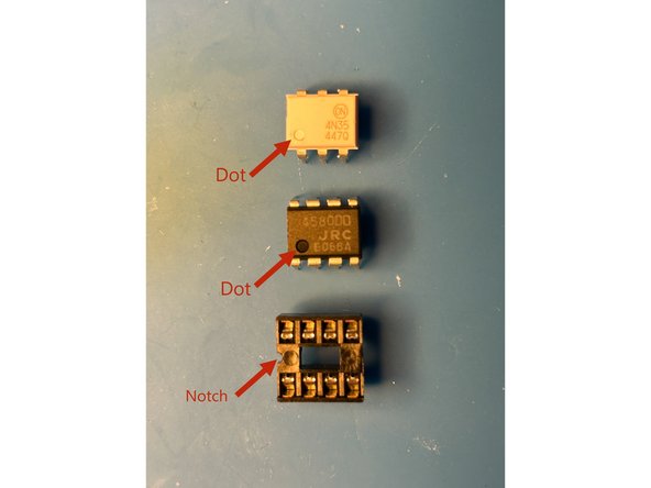
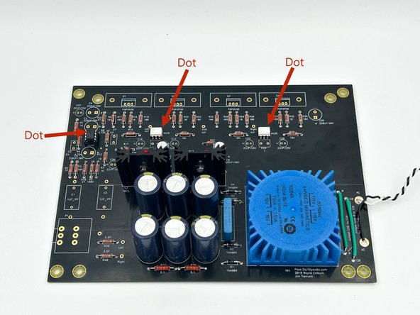
Make sure to properly orient the Optocouplers, OpAmp Socket, and OpAmp. Pin one is designated with a dot on the package of both the optocoupler and the opamp. The notch on the OpAmp socket should align with the notch designated on the PCB silkscreen. The OpAmp and the Optocouplers should be installed with the dot closest to the notch.
-
Install the OpAmp socket ensuring that the notch on the socket matches the silkscreen.
-
Gently install (do not solder) the OpAmp, U1, into the OpAmp socket. Be gentle with the OpAmp pins.
-
Install both optocouplers, U4 and U5. Ensure the dot is closest to the notch marking on the silkscreen.
-
Photo 1 - Optocoupler (top), OpAmp (middle), and OpAmp Socket (bottom) all in the same orientation with the dots matching the notch.
-
Photo 2 - OpAmp Socket, OpAmp, and both optocouplers installed. Note the orientation.
-
-
-
Verify the orientation of the electrolytic capacitors! The negative side a.k.a. the cathode is indicated with a band. The cathode lead is the shorter of the two leads. The positive side a.k.a. the anode is the longer of the two leads. The anode aligns with the square pad. A (+) is also indicated on the silkscreen.
-
Install C12, C17, C22, C25, C26, C27.
-
Install C13 and C23
-
Install C1 and C5
-
Install C3 and C4. Optionally, these may be installed on the bottom of the PCB to make room for larger op-amps.
-
Observant DIYers may have noticed the silkscreen and schematic note 50V caps. 25V is perfect for a standard build.
-
Install C9 and C28.
-
Photo 1 - All caps installed.
-
-
-
Install the volume pot. Ensure that it is sitting flush with the PCB.
-
Remove the washer and nut from the volume pot and save them for later.
-
Photo 1 - Volume pot installed.
-
-
-
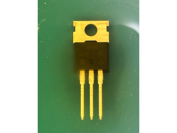
It is critical to identify and separate the output MOSFETs.
-
The 610 are the N-Channel MOSFETs. They will be installed in the Q1 and Q3 locations. Note - The boards are marked with FQP3N30. These were the MOSFETs included in the original kits.
-
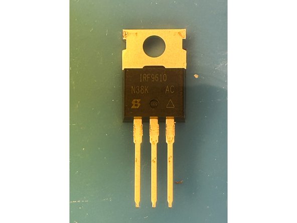
The 9610 are the P-Channel MOSFETs. They will be installed in the Q2 amd Q4 locations. Note - The boards are marked with FQP3P20. These were the MOSFETs included in the original kits.
-
Photo 1 - 610 MOSFET. Apologies for the poor quality. View the photo in full screen.
-
Photo 2 - 9610 MOSFET. Apologies for the poor quality. View the photo in full screen.
-
Identify and separate your MOSFETs. Mark them with a gel pen or use whatever your favorite method may be to keep them easily identified and separated.
-
-
-
Triple check the location of the MOSFETs prior to soldering.
-
The same technique is used in this step as was used to install the voltage regulators.
-
Install the MOSFETs - Q1, Q2, Q3, and Q4.
-
Photo 1 - MOSFETs installed.
-
-
-
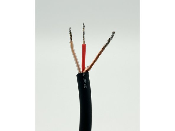
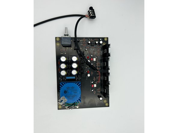
Cut the Mogami signal wire into 3 pieces. There is a little extra wire, but not much. Measure twice, cut once. Label the wires. It is easy to mix them up before soldering.
-
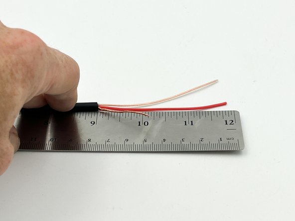
Approximately 14" (35.5cm) for the pre-amp output wiring
-
Approximately 12" (30.5cm) for the input wiring
-
Approximately 10" (25.5cm) for the headphone output wiring
-
For the 10" and 14" cuts - Strip the outer insulation approximately 3/4" (2cm) and the insulation of the red / clear wires approximately 1/8" (3mm). Exact length is not critical.
-
Twist the bare copper shield wire tightly, and tin the ends of all wires.
-
Photo 1 - Wire prepped for installation.
-
-
-
The kit includes a switched Headphone Input Jack. When no headphone jack is inserted, the output is sent to the pre-amp outputs. When a male 1/4" TRS headphone jack is inserted, the output is sent to the headphone jack. DO NOT plug in or unplug headphones or connect pre-amp outputs with the WHAMMY powered up.
-
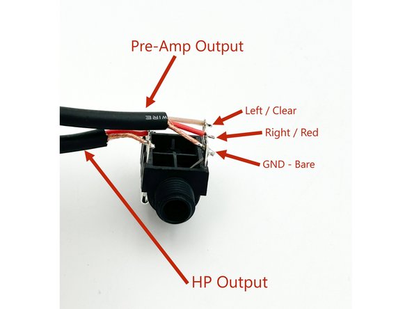
It is critical to wire the headphone output and pre-amp output appropriately.
-
Solder the 14" pre-amp out and 10" HP out wires to the headphone jack exactly as shown in the photo.
-
Photo 1 - HP Jack with wiring.
-
-
-
For the 10" HP out wire connected to the HP jack. Strip the outer insulation approximately 3"(8cm) and the insulation of the red / clear wires approximately 1/8"(3mm). Cut the bare wire to approximately 1"(2.5cm). Exact length is not critical.
-
Remove approximately 1/3 of the strands of the exposed bare copper shield wire (it's too large for the PCB). Twist the bare copper shield wire tightly, and tin the ends of all wires.
-
Solder the HP output wire to the PCB:
-
Red - Right Out
-
Clear - Left Out
-
Bare Wire - GND Out
-
Photo 1 - HP output wiring installed.
-
-
-
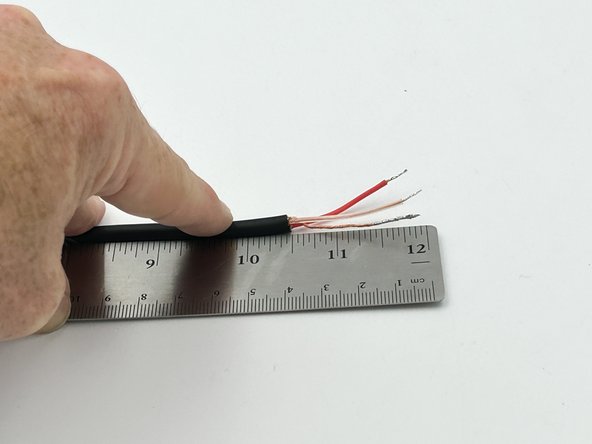
For the 12" cut - Strip the outer insulation approximately 1.5"(4cm) and the insulation of the red / clear wires approximately 1/8"(3mm). Exact length is not critical.
-
Remove / trim roughly 1/3 of the strands of the exposed bare copper shield wire (it's too large for the PCB). Twist the bare copper shield wire tightly, and tin the ends of all wires.
-
Photo 1 - Input wire tinned and ready to install.
-
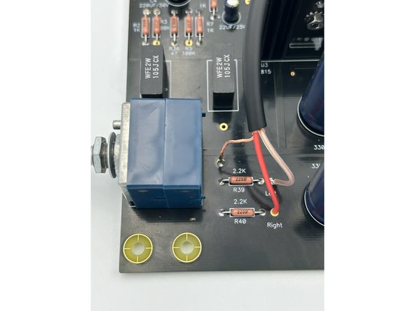
Solder the Input wire to the PCB.
-
Red - Right
-
Clear - Left
-
Bare wire - Unlabeled pad next to R39
-
Photo 2 - Input Wiring Installed
-
-
-
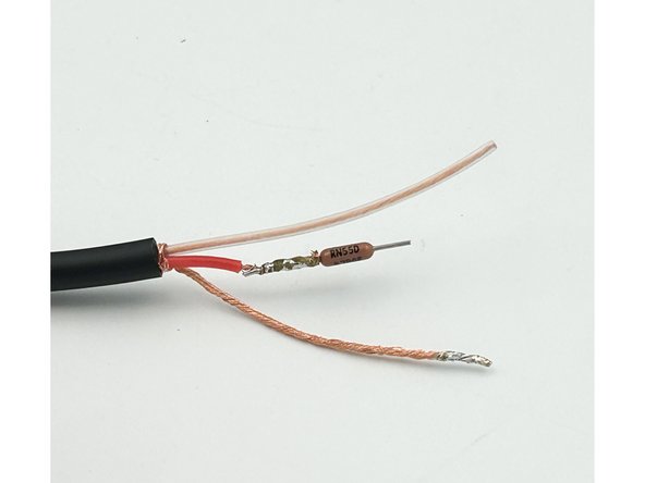
Strip approximately 2"(50mm) of the outer insulation from the non-connected end of the pre-amp input wire. Twist and tin the bare-wire conductor. Strip the red and clear insulated conductors leaving a few mm of insulation remaining.
-
Wind the red (or clear) conductor around the leg of a 47R resistor keeping the winding close to the body of the resistor. 5 or 6 winds is fine. The goal is a solid, but short, connection. Solder the wire to the resistor. Trim the remaining wire and the remaining resistor lead. Trim the other end of the resistor leaving about 5mm.
-
Photo 1 - Resistor attached to red-insulated conductor.
-
Attach the other conductor (red or clear) to the remaining 47R resistor similarly.
-
Cut enough heatshrink tubing to cover the the body of the resistors, the soldered joints, and a little bit of the insulation. Use a heat gun or other appropriate method to shrink the tubing into place.
-
Photo 2 - Completed assembly for the pre-amp output wiring.
-
-
-
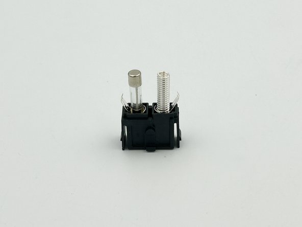
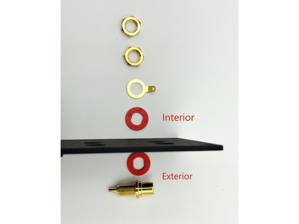
The installation order is critical for the RCA jacks. The jacks ship with the ground tab between the two insulators. You must have the ground tab isolated from the chassis.
-
Photo 1 - Correct orientation for RCA jack components.
-
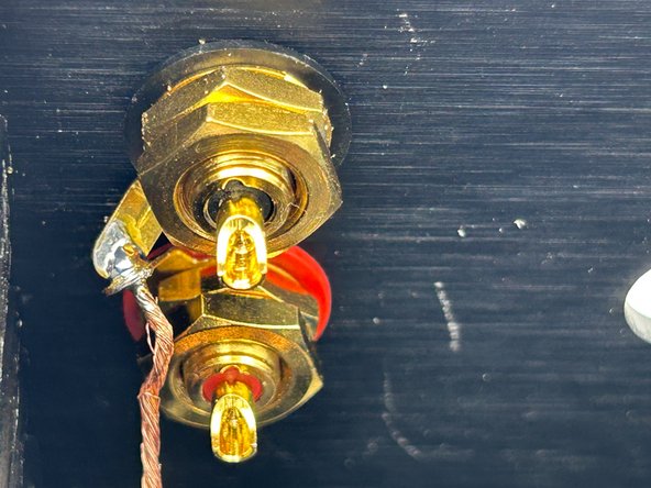
Install both the left and right pre-amp output RCA jacks. As shown in photo 2.
-
Insert the ground wire through both ground tabs. Slide the ground tab onto the lower (red) jack. Loosely install the first nut on the red jack. Slide the ground tab onto the upper jack (black) and install the first nut. Fully tighten the nuts ensuring that the solder cups for the jacks are oriented upward. Install and tighten the top nuts.
-
Solder the ground wire to both tabs.
-
Photo 2 - Pre-amp output jacks installed and ground wire connected to both jacks.
-
-
-
Add solder to the RCA jack solder cups.
-
Solder the tips of the 47R resistors to the jacks. It is generally easier to solder the lower jack first. Ensure you have the red insulated wire installed to the red (lower) jack and the clear insulated wire installed to the black (upper) jack.
-
Check for shorts and proper continuity from the back panel jacks to the headphone jack. Fix any potential issues before proceeding.
-
-
-
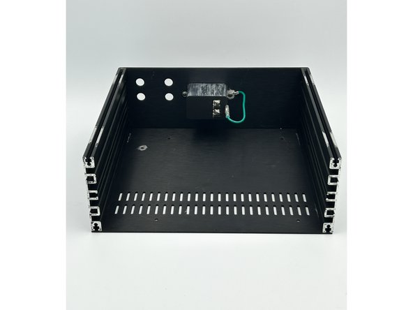
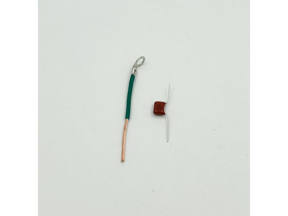
Cut approximately 3"(8cm) of the green wire. Install a ring connector to one end using the same process as the mains earth connection. Strip a little over an inch of the insulation from the remaining end of the green wire. Bend the legs of the 0.1uF film cap as shown in photo 1.
-
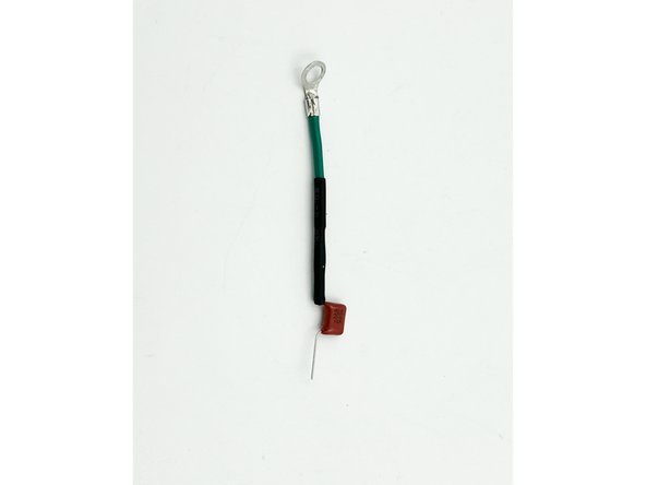
Slide a piece of heatshrink tubing over the green wire. Gently wrap one leg of the capacitor around the wire keeping the cap in-line with the wire. Solder the cap to the wire. Trim the cap leg and any excess wire. Shrink the tubing in place covering the joint.
-
Photo 1 - Complete ground wire and cap assembly.
-
The cap allows any RF present on the input to go to GND. This improves performance and may prevent oscillation with some OpAmps.
-
-
-
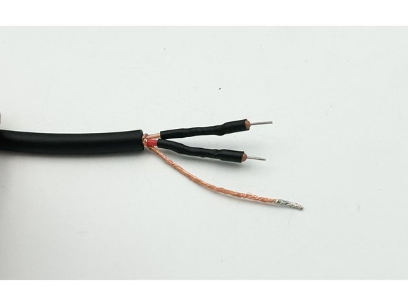
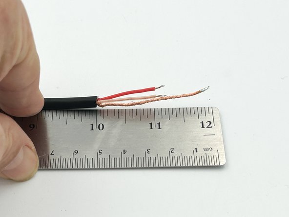
Strip off approximately 2"(5cm) of the outer insulation from the input wire. Cut off approximately 1"(2.5cm) of the red and clear insulated conductors. Strip approximately 1/8"(3mm) from the red and clear insulation. Twist and tin all wires.
-
Photo 1 - Input wire prepped for soldering
-
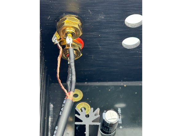
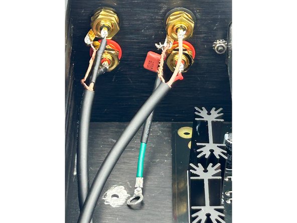
Install the RCA jacks and ground wire using the same method used for the pre-amp output wiring. Slide the capacitor lead through one of the ground tabs and solder the assembly in place.
-
Solder the red and clear insulated input wiring to the red and black input jacks respectively.
-
Photo 2 - Input wiring installed.
-
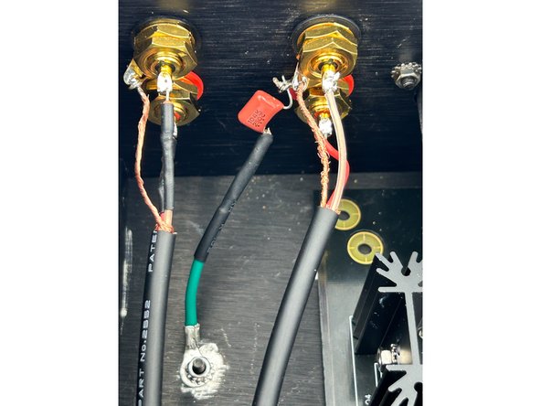
Securely connect the ground lug to the chassis using the black M3 x 8mm cap head screw and a keps nut.
-
Photo 3 - All back panel wiring complete.
-
-
-
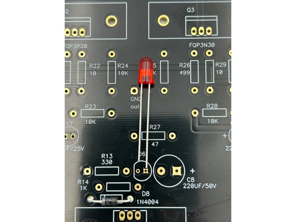
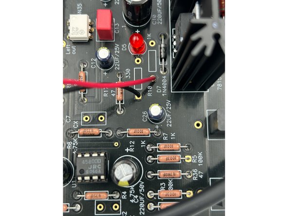
Trim approximately 1"(25mm) from the LED leads. Strip and re-tin the wires.
-
Install the LED wires on the pads for R9 and R10 as shown in photo 1. The polarity is critical. Check with a DMM prior to installation if you are unsure.
-
Photo 1 - LED wiring location.
-
If you removed the standoffs from the chassis in step 44, reinstall the standoffs and secure the PCB to the standoffs using the M3 nuts.
-
Slide the mains wiring over the appropriate slots on the PEM and ensure that the the insulating boots completely cover the slots on the PEM and that the connection is secure.
-
Those that appreciate additional coverage and/or if it is required by local code may choose to add liquid electrical tape or other means to ensure no unintentional contact with mains voltage if the unit is being serviced.
-
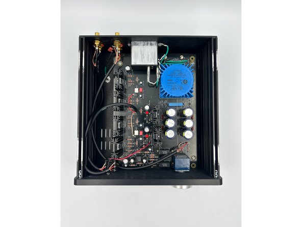
Photo 2 - Congratulations! All the wiring is complete.
-
-
-
Ensure that you have the M3 nuts inserted into the side rails for attaching the top panel.
-
Using the black M4 cap-head screws included with your chassis, install the front panel. The front panel should fit perfectly over the volume pot.
-
Slide the headphone jack and the LED into place.
-
Photo 1 - HP Jack and LED in place.
-
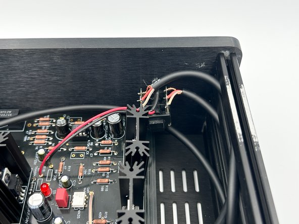
Install the black washer and red (or black) nut onto the headphone jack. Install the washer and nut onto the volume pot. Install the volume knob, and route wiring as necessary.
-
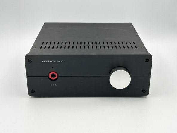
Photo 2 - HP Jack Secured and Volume knob installed.
-
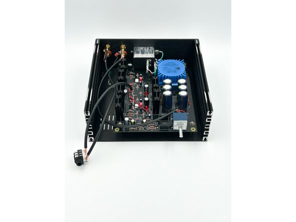
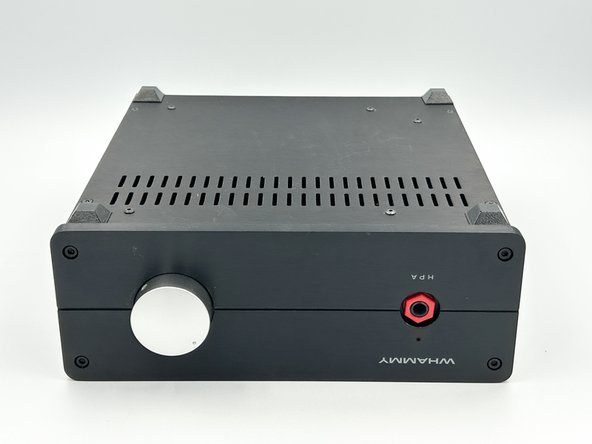
Photo 3 - Ready for testing.
-
-
-
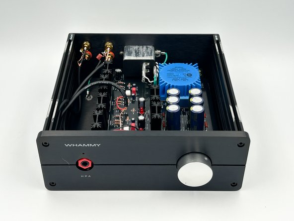
Listen to a few of your favorite songs and conduct any objective / subjective testing before installing the top panel. Rumor has it, that it's bad luck to install the top panel before listening to a few songs.
-
If it's not performing to expectations, pause and troubleshoot.
-
Ask questions and post your build photos in the WHAMMY thread on diyAudio.com
-
Install the large adhesive feet. These provide a little more clearance and are more stable than the feet included with the chassis. Be cautious. They cannot be moved (easily) after they are pressed into place.
-
Photo 1 - Feet installed. It is builder's choice for placement. It was easiest to install them on the 4 corners for alignment in this builder's opinion.
-
Install the top panel.
-
Photo 2 - Congratulations on completing your WHAMMY!
-


Congratulations on building the WHAMMY!
A few things before you run off and start another project:
- This is a build guide by DIYers for DIYers. If you have any suggestions for improvement, notice any errors, or think something could be clarified, please post in the forums. Someone will be looking.
- Please post some pictures of your build in the forum. Nothing makes us happier than seeing completed builds and the creativity of DIYers around the world.
- Make sure to go to the forums and thank Wayne for another amazing project.
- Last but not least, please click the button below if you completed the amp. It really helps the data dorks.
Cancel: I did not complete this guide.
One other person completed this guide.