
-
-
This is the build guide for the Nelson Pass DIY Sony Vfet amplifier, P-channel, from spring 2021.
-
-
-
Nelson's great write up can be found here - https://www.diyaudio.com/forums/attachme...
-
Remember you can click into each photo to see it in huge detail.
-
-
-
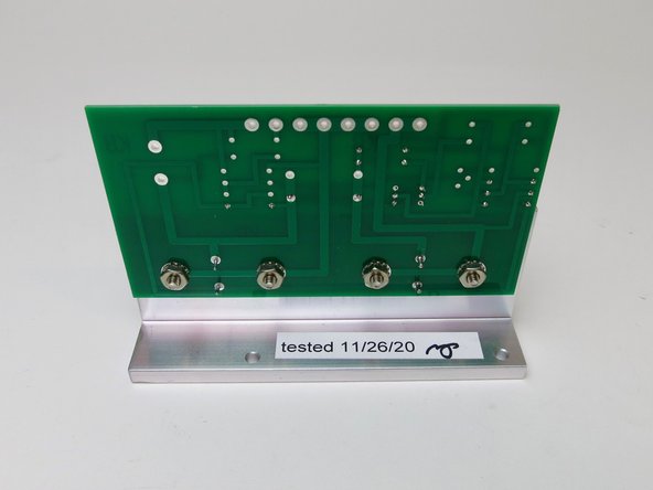
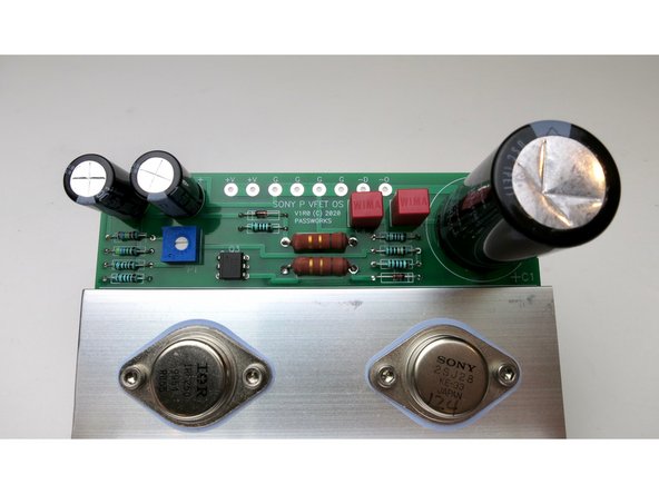
The P channel output board comes partly assembled and tested by Nelson Pass himself.
-
-
-
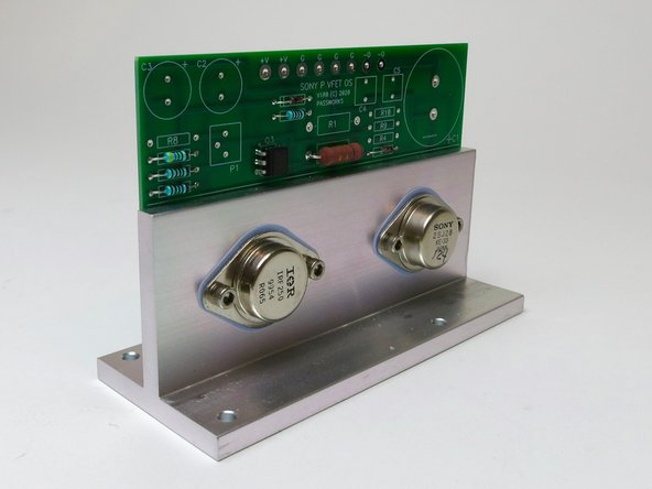
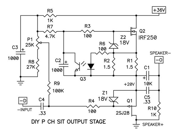
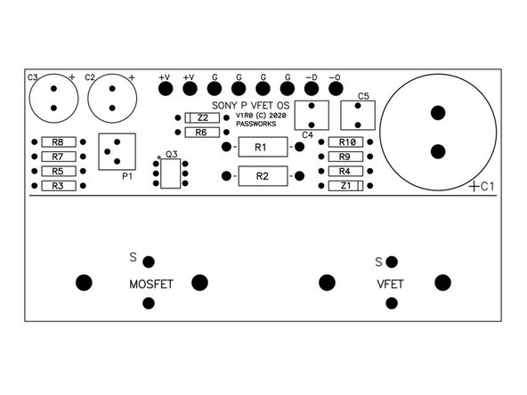
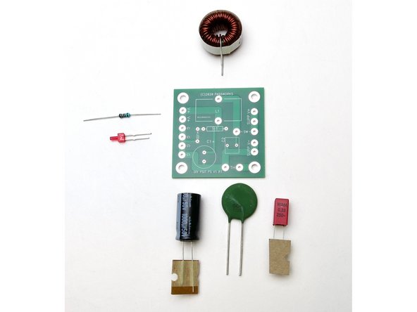
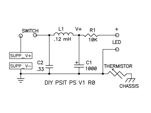
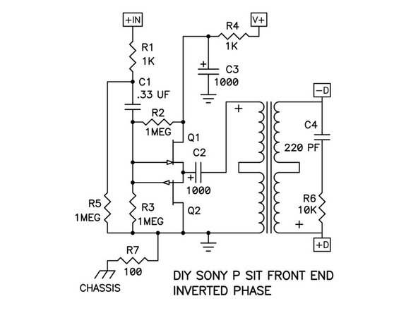
Schematic, Diagram and stuffed output board.
-
-
-
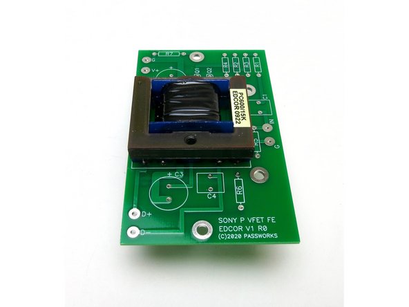
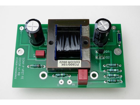
Front end board for P-Channel amp.
-
-
-
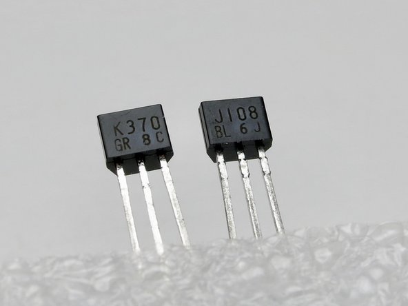
Jfets are difficult to read, K370 is the N channel, J108 is the P channel.
-
Q1 is N
-
Q2 is P
-
Alternatively, the kit may be supplied with Linear Systems LSK170 (N) and LSJ74 (P)
-
-
-
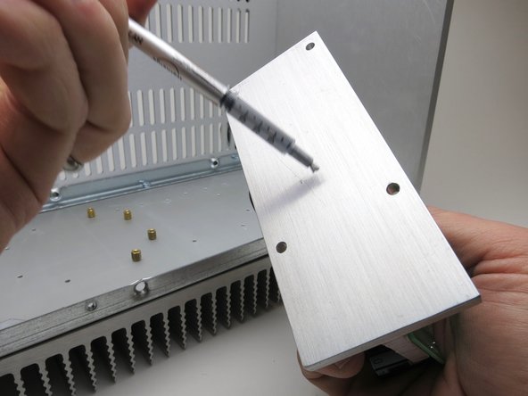
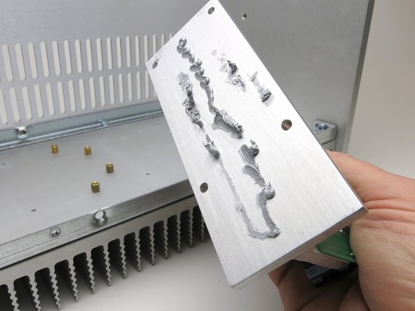
Peel the label from the syringe of thermal paste, to view the entire volume. Spread 1/2 the syringe on each T-bracket.
-
Smear it all over, try to get it smooth over the entirety of the interface.
-
This interface does not need to be electrically isolated and so the thermal goop is conductive, hence the metallic color.
-
-
-
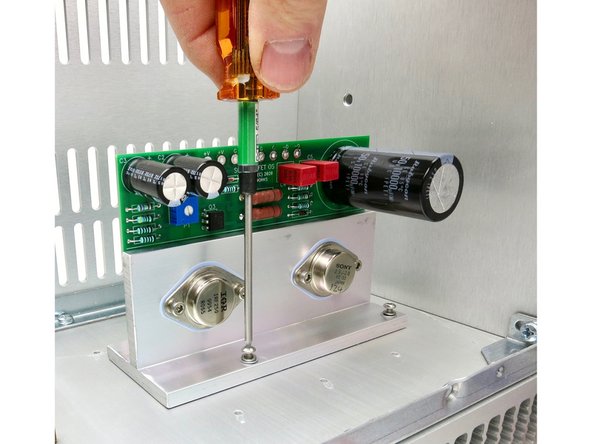
Attach output stage to the heatsink.
-
Mount them with components up, and mount towards the front of the chassis.
-
They are not mirror image.
-
Arrange them so they use the heatsink holes nearest the front of the chassis.
Note the use of both a flat and split washer underneath each mounting screw. These are necessary to prevent the screws from bottoming out in the mounting holes.
-
-
-
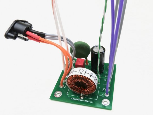
The PSU filter is a simple CLC filter. This helps attenuate any residual switching noise of the PSU brick.
-
The brick is already very low noise and high performance. The filter doesn’t need to do very much, and the combination of the Mean Well and the filter yields a very quiet supply.
-
You have a choice between red and blue LED, use whichever you prefer. Or supply your own if you want some of the new LED colors available in the last year or two.
-
-
-
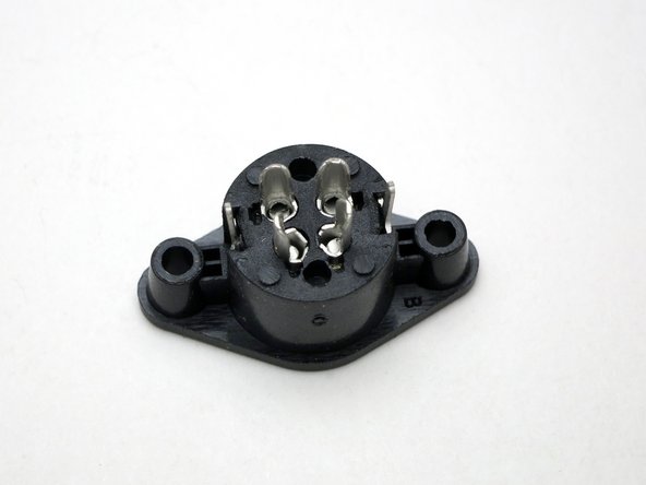
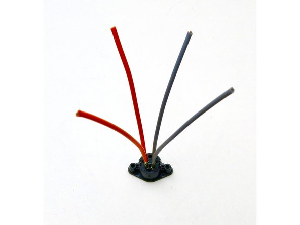
Be careful and deliberate soldering the wires to the pins, trim back your insulation precisely and make good clean joints - the plastic is fairly easy to melt.
-
Use approximately 90mm (3.5in.) of wire for each pin.
-
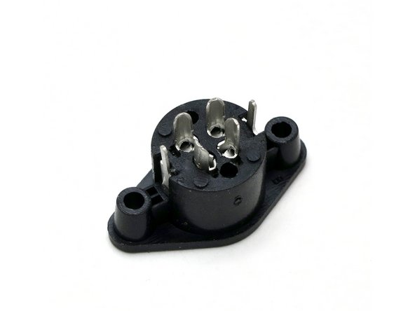
The DIN socket is mounted to the inside of the back panel with the wider pins on top. (As shown)
-
-
-
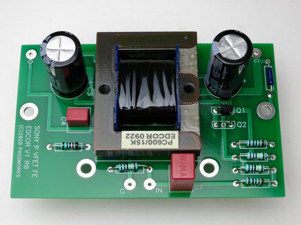
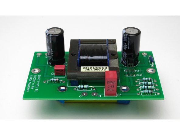
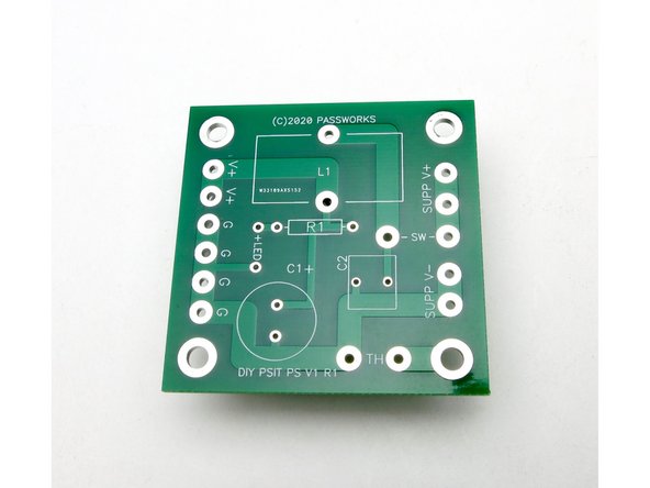
Stuff the PCB as shown on the schematic.
-
You want to save a little of your insulation from the wires and add that to the legs of the green NTC thermistor to raise it up off the PCB a little - this will help make room for your tools when attaching it to the chassis floor.
-
Wires to switch should be approximately 150mm (6in.)
Make sure the DC inlet connector is connected with the correct orientation. Relative to these photos, the small notch is on the upper side. This will correspond to the flat portion of the connector on the cable from the SMPS brick.
-
-
-
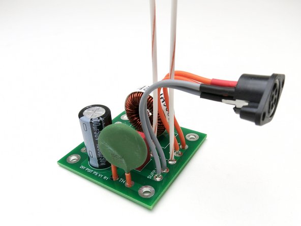
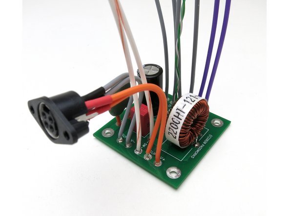
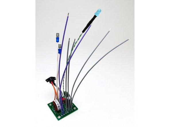
This is the most important photo of this guide - all the wires need to be soldered onto the filter before installation. There is no room to get your iron onto the filter board once it’s mounted.
-
Use whatever colors you like, in this example I’ve used -
-
ORANGE V+ from DIN (90mm) GRAY Ground 150mm (6in.) to input stage, 200mm (8in.) to output stage PURPLE V+ to output stages 200mm (8in.). WHITE to switch 150mm (6in.)
-
Twisted Pair to LED 230mm (8in.)
-
There may not be enough wire in the early kits to stick exactly to the color scheme... if you run out of a particular color, of course you can substitute another color.
-
Use your own wire if you desire. But the provided is wonderful mil-spec silver plated copper with PTFE insulation. It can be a challenge to strip sometimes, use this as opportunity to buy a really nice wire strippers.
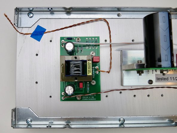
Note: if you plan to pre-assemble your filter board to the chassis bottom plate, notice that the bottom and top vented panels are directional. The front end aligns flush to the heat sink, while the rear end sticks out 3mm past the heat sink, in order to align flush to the rear panel. See photo in step 18.
-
-
-
Nelson’s input stage for the P-channel (hence, "Nelson P") output stage is included and shown here.
-
Photo 3 - Stuffed PCB
-
-
-
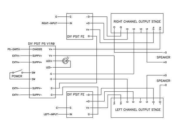
Print these out as big as you can and have them in front of you when wiring the amp.
-
Seriously. Print them.
-
There are a lot of connections spread out over 5 PCBS and the back panel. Be deliberate and take your time, double check everything.
-
Yes, the speaker red post is connected to ground, and the black post to the outputsage’s output. (Labeled “-O” )
-
Click on the wiring diagrams so they open up in a new window at full resolution. Then print them. :)
-
-
-
Images to assist in wiring.
-
-
-
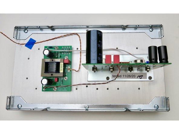
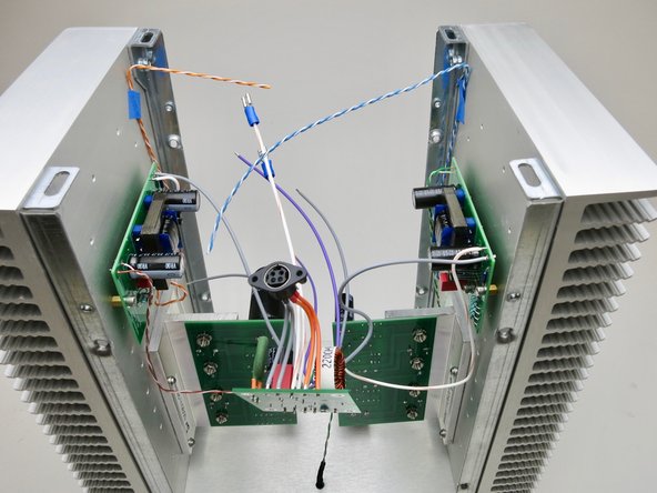
Build as much as you can on the heatsink before assembling the chassis.
-
Once together there is little room for your hands and tools in the chassis.
-
Tape is there only to keep input wire in place during assembly.
-
-
-
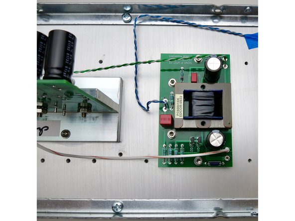
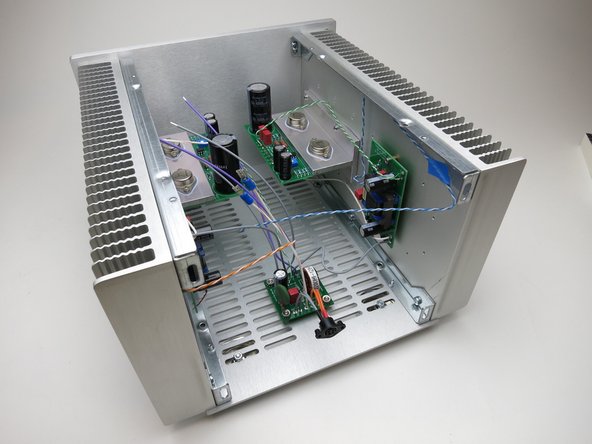
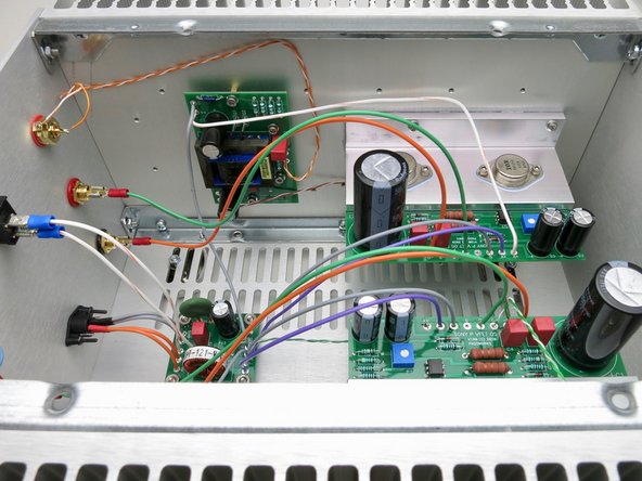
Photos to help show connections.
-
-
-
Attach only when all the wiring on Front End and Output Stage boards is completed,
-
AND only when the heatsinks are properly attached to the front panel.
-
-
-
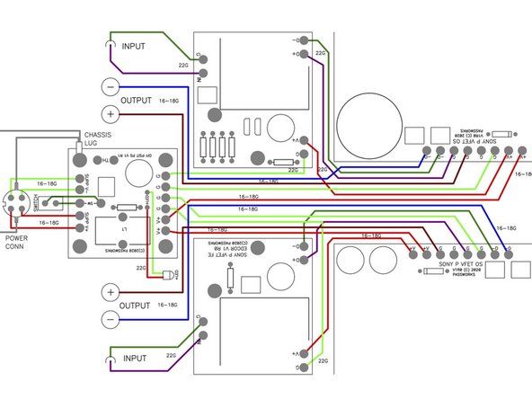
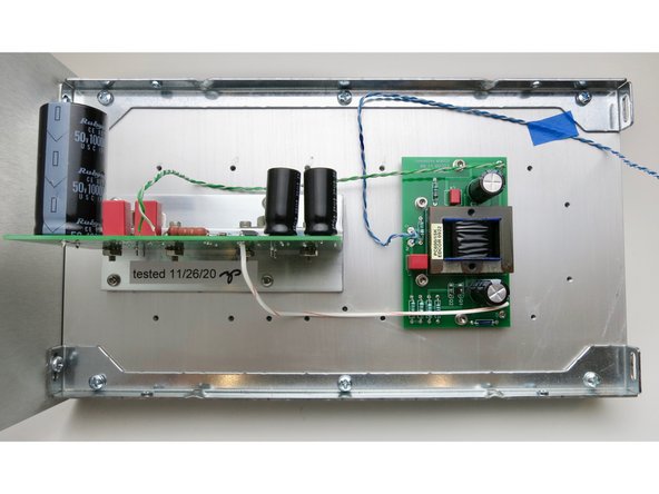
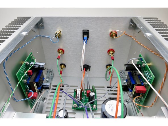
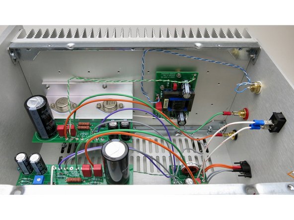
Back panel and bottom panel connections on completed amplifier.
-
-
-
Wires to speaker posts are approximately 250mm (10in.)
-
Yes, output ground attaches to speaker RED.
-
-
-
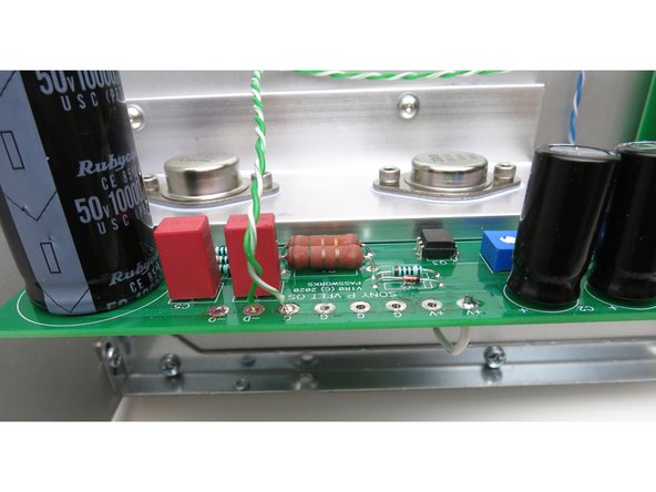
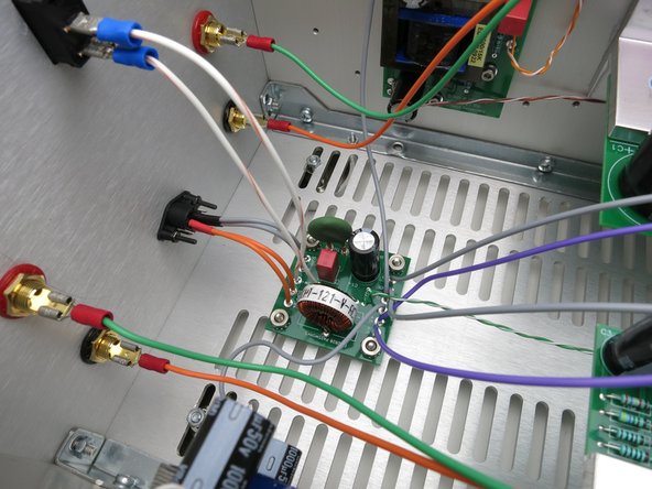
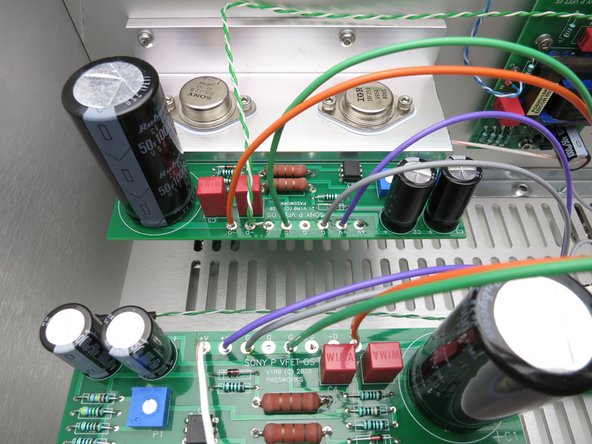
Output Board connections.
-
-
-
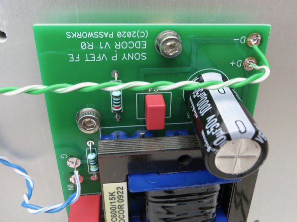
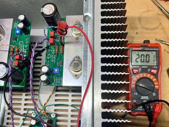
Select multimeter to DCV
-
Red probe to the anode side (the side without the line) of Z1, the zener closest to the Vfet
-
Black probe to ground
-
Slowly adjust potentiometer until you read 20V
-


Cancel: I did not complete this guide.
5 other people completed this guide.