
Introduction
What Are We Building?
This guide covers the assembly of the Nelson Pass VFET amplifier created to celebrate the 25th anniversary of diyAudio.com. A limited number of these kits were made available to DIYers. The kits also came with an optional front end board created by Mark Johnson. This guide does not cover the assembly and use of Mark's boards.
|
What Is Covered In The Guide?
This is a build 'guide'. It is not an instruction manual. The purpose is to assist in learning and guide DIYers with helpful information. Builders should not expect every detail to be covered.
|
It is not the only information needed to complete the project. Some additional links are included as guidance. It is critical to understand that the guide is intended to be a representation of how to complete the project. It is not the only way to complete the project. Builders that are unsure may want to begin with the assembly outlined in this guide, ensure that they have a working amplifier, and then decide if they'd like to make any modifications. It's DIY, choose your own adventure and have fun. With that said, these are the last of the VFETs, so please exercise caution.
|
The project is considered moderately difficult. The guide is not intended to instruct someone that has never built an audio amplifier through their first project. This guide is best suited to someone with an interest in audio electronics that has built one or two audio projects and needs a few helpful hints. There are a few places where particular attention is required, and the wiring may be challenging. A very basic wiring diagram is provided for both the N and P channel versions. The P channel amplifier has a wiring scheme that may be unfamiliar or even confusing. It is highly recommended to review the documents thoroughly before soldering the wiring. Even the most seasoned of builders may want to review the phase inversions.
|
Builders should have a basic knowledge of electronics and should be proficient in through-hole PCB soldering. Although there are many helpful tips throughout the guide, before attempting to build this project, the builder should be confident in their ability to:
- follow a schematic and identify the proper placement of parts from the schematic onto the PCB,
- understand basic measurements to identify parts correctly, and
- properly solder a variety of through-hole components.
|
What Else Do You Need?
Everything you need to assemble a working amplifier is included in your kit minus the tools. However, we've suggested a few helpful tools, just in case.
|
Most importantly, if you have questions, please seek help in the forum.
Enjoy!!!
Tools
Parts
No parts specified.
-
-
A black bullet is an instruction or valuable information.
-
Everything in this guide is important, but here's how you'll know something is REALLY important.
-
A green bullet is the mark to do something.
-
A yellow bullet indicates a fun fact.
-
Warnings will be noted with a warning symbol and bold, red, underlined text. Pay Attention!
-
Tips and tricks and helpful reminders will be noted with an information bullet.
-
Photo / Image captions and information will be noted with the Photo/Image Icon.
-
-
-
Click on the image to enlarge and read the warnings carefully.
-
-
-
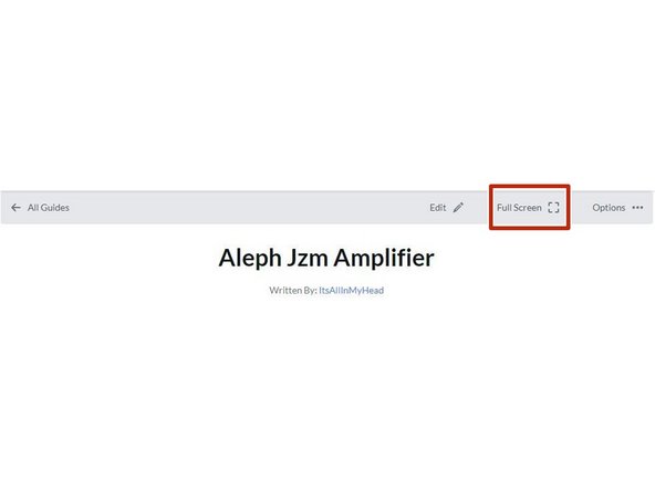
Your first "real" black bullet. You may notice that you have the option to view in "Full Screen". I like it either way, but I prefer full screen. This web platform works well with tablets too. I've tested it with various monitors of various aspect ratios and tablets. Choose what looks best to you. The printed .pdf format is nice too.
-
Image 1 - If you don't know how to get to "Full screen", take note of the box around "Full screen" at the top of the guide above the header / title. That's where you click to move to Full Screen.
-
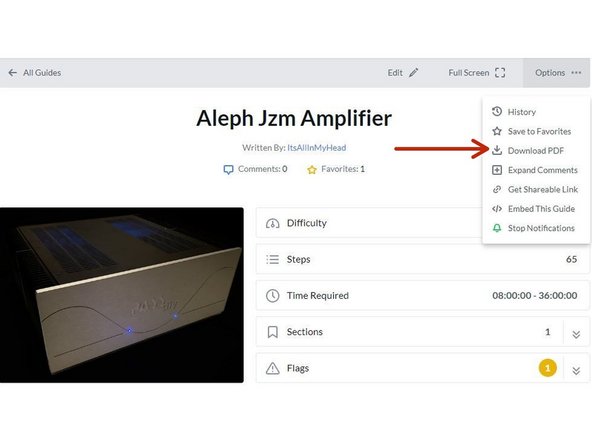
Image 2 - If you don't know how to print the document. Note that you can download this guide as a .pdf and print it.
-
In all the on-line views, if there are multiple images and/or photos within a step, mouse-over or tap/click as appropriate to make which ever one you'd like the primary image (the biggest one).
-
Mousing over / tapping on the primary image will change the cursor to a magnifying glass. Clicking / double tapping will open a new tab or enlarge and center the image on your screen.
-
In full-screen mode, the keyboard right and left arrows or clicking the arrows in the upper right will advance or reverse one step.
-
Your first "real" green bullet. Choose if you want to view in full screen or standard (if you haven't already) and/or print a copy of the guide.
-
Get started. Move on to step 4.
-
-
-
All mistakes are preventable, and this guide moves slowly through each step.
-
The most common issues with builds are mis-stuffed parts and poor solder joints.
-
Symptoms from mis-stuffed parts typically manifest quickly. For this build, pay particular attention to the small resistors and the TO-92 packaged transistors. The impact from an improper part placement can be benign, or you could release the "magic smoke".
-
The impact of poor soldering varies. A short/bridge that will impact your build is unlikely, but can be catastrophic. More commonly, the issues are partial coverage or a cold joint. Symptoms may not manifest until you least expect them, and they may be intermittent. Inspect each and every joint under magnification. You'll be glad you did.
-
DMM issues can lead to frustration.
-
Check the batteries. When in doubt, replace the batteries.
-
Make sure your probes are reading "0 Ohms" resistance probe to probe or are appropriately compensated.
-
Make sure your probes are connected properly. For this guide, the polarity of the voltage being read, but it's best practice to always observe and report polarity. If you are troubleshooting, it is likely the polarity will matter.
-
-
-
The notation of voltages requiring a decimal place will have a "V" in place of the decimal. 24V5 is 24.5 Volts or 24,5 Volts.
-
The notation of resistance requiring a decimal place will have a "R" in place of the decimal. 0R5 is 0.5 Ohms or 0,5 Ohms.
-
The notation of Amperage requiring a decimal place will have an "A" in place of the decimal. 1A1 is 1.1 or 1,1 Amperes.
-
-
-
The most common action you'll take throughout the guide is to "install" your parts AKA stuff the PCB. Parts installation includes:
-
Ensuring you have the correct parts to match the PCB silkscreen / schematic.
-
Ensuring the leads are bent to the proper pitch (if applicable).
-
Inserting the part into the boards along with any vertical spacing (as noted and applicable).
-
Soldering the parts into place.
-
Cutting the leads to the proper length*
-
It is also acceptable to clip the leads to the correct length prior to soldering. There are compelling reasons to do it either way. If you are unsure, watch a few videos, read a few articles, and do some test soldering of your own to see what works best for you. If you choose to clip prior to soldering, use the correct tool.
-
Cleaning and inspecting the joint. It is strongly recommended to use magnification and good lighting to inspect each and every joint.
-
-
-
This guide does not cover how to solder / install through hole parts. There are a variety of great ways to install a part and achieve a proper solder joint, but there are common themes throughout. Below are a few links. See what works best for you. Neither diyAudio nor the author have any affiliation with any of the companies or persons linked.
-
-
-
-
-
Image 1 - A basic soldering sequence and examples of both good and poor joints. Taken from the Rayming PCB & Assembly Guide linked above.
-
The key variables to soldering are the type of solder chosen, the tip used, and the tip temperature. These all vary widely between users and are inter-related. If you are new to electronics, the best solution is practice. Scrap electronics and inexpensive parts are a wonderful way to learn.
-
Leaving the iron tip on the joint for longer than around 5 seconds is not a substitute for too small an iron tip or too low a temperature. If you need to reflow a joint, or if the solder isn't flowing, flux is your friend.
-
-
-
The builder must ensure all terminations are done properly for safe and trouble-free operation.
-
It is often discussed whether to solder and/or crimp or whether spade-type connections are worthy of a "good" build. In the author's opinion, a properly-crimped connection using high quality terminations and a proper crimper is an excellent choice. Adding a bit of solder can't hurt, but it will never "fix" an improper crimp.
-
The advantage is that many crimped terminations allow flexibility.
-
The disadvantage is that a proper crimp is only achievable when using a proper tool, and many people don't have a proper crimper for each type of termination.
-
The video linked does an excellent job of demonstrating various crimps. You are strongly encouraged to watch it. Excellent Crimping Video. Note - Neither the author nor DIYAudio have any affiliation with the video's creator.
-
-
-
Plan your build. Read this guide a few times before you even take the first part out of the bag.
-
Go slowly. You're not getting paid to do 100 boards a day. This should be relaxing and fun. A lot of errors can be traced back to lack of attention and rushing.
-
The ONLY parts within reach should be for the step you are working on at the moment. Many parts look very similar.
-
Move the boards and your body around to give yourself the best angle to solder each part. Get close to your work and use magnification. A well-lit workspace is important. You don't stand a chance if you can't see.
-
Before moving to the next part, triple check your work. Hopefully you won't make any errors, but it is much easier to remove one part than many to fix an error. Using the included documents and following a basic sequence will assist with error-free construction.
-
Take plenty of breaks and stop at any point confusion or frustration sets in. There are a few recommended stopping points throughout the guide, but stop any time you mentally or physically need to recharge.
-
Try to keep distractions to a minimum.
-
Neatness counts!!! Take pride in your work. You'll be happy you did.
-
-
-
Print a copies of each the documents found at the end of this guide or in the Documents Tab if you are viewing in Full-Screen Mode. You'll need to go back to the Introduction (full-screen mode) or scroll to the end of the guide to find the documents / documents tab.
-
Tidy up your workspace. Keep in mind that you'll be working with a very hot soldering iron, and it can be easy to misplace parts. A few recomemndations:
-
No other parts for any other projects should be within arm's reach.
-
The floor and the area around the workspace should be clean, just in case a part escapes.
-
-
-
Most of the photos in this guide show the P-channel amplifier. The differences are only in how the boards are wired. Pay close attention to the wiring diagrams. It is recommended to print out a wiring diagram and cross off the wiring as you progress through the build.
-
Any time there is a critical difference between the P-Channel and N-channel, it will be noted with the Warning, and will be displayed like this. This format is typically reserved for safety cautions / warnings, so it should get your attention.
-
-
-
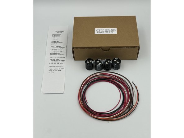
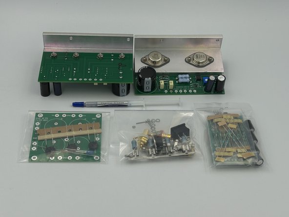
Check to ensure you have all the primary bags / components / assemblies. Do not open the bags at this time.
-
Photo 1 - Contents of main box (1) - Note: your contents won't be identical. Some updates were made after prototyping / before shipping.
-
Photo 2 - Contents of main box (2) - Note: your contents won't be identical. Some updates were made after prototyping / before shipping.
-
Photo 3 - Contents of Interior Box - Note: your contents won't be identical. Some updates were made after prototyping / before shipping.
-
Note - How cool is it that Nelson initialed the output stage boards?!
-
The output stage boards come fully assembled, tested, and adjusted to the "sweet spot" by Nelson Pass himself. Only the bravest (or perhaps most foolish) DIYers will touch P1. If you are among the brave, but intelligent, please wait.
-
-
-
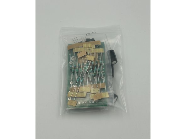
Carefully remove the contents of the bag containing all the parts for your Front End into a bowl or onto a clean work surface.
-
Photo 1 - FE 2022 Parts Bag
-
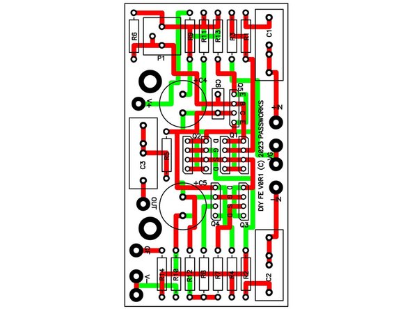
For a better understanding of this versatile circuit, read and/or print the FE2022 documents from the documents section of the guide and review the schematic and board layout. There are some important things to note during assembly that may not be intuitive to all builders.
-
C6, P1, and R14 are not installed.
-
Jumpers are required in the place of C3 and R10.
-
Photo 3 - FE2022 V0R1 Board Layout
-
-
-
Assemble the FE2022 boards. A good assembly order might be:
-
Resistors and jumpers. Use spare resistor leads to jumper R10 and C3.
-
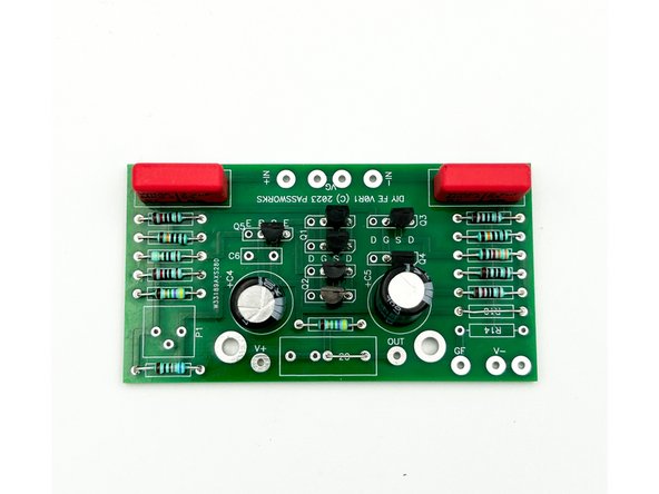
Transistors. Take specific note that the boards are cleverly designed to allow multiple pin orientations for various transistors.
-
Confirm for the pin-out of the transistors using your handy tester. The J113 are D,S,G (Pins 1,2,3). The KSA992 is E,C,B (Pins 1,2,3).
-
Make sure you install the parts using the proper pads. There are 4 pads for 3 legs. One is left empty. If you're unsure, test the parts ... or just copy the photo exactly.
-
Film capacitors and Electrolytic capacitors - Ensure proper orientation for the electrolytic capacitors. The silkscreen notes the (+) terminal.
-
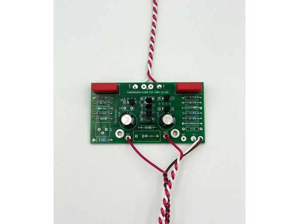
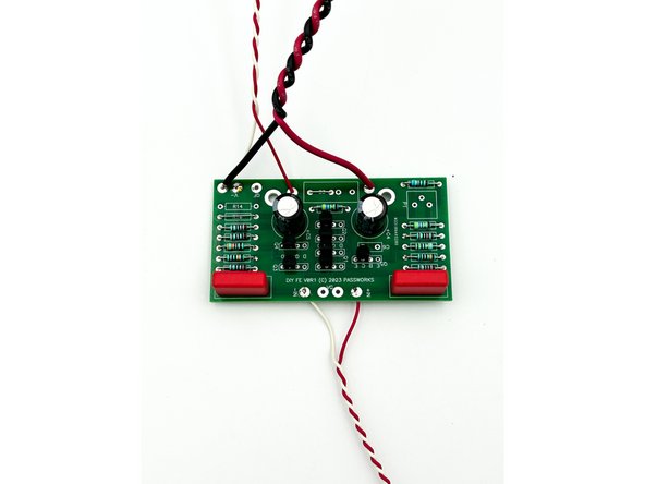
Photo 1 - The front of your board should look a lot like this. Pay attention to the placement and orientation of the transistors. Note - The flux was promptly cleaned from the In+ and V- pads after the photo. ;)
-
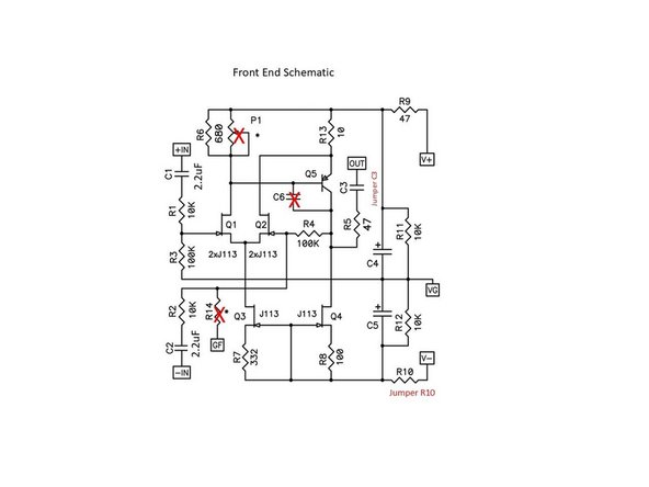
Image 1 - Front End Schematic
-
-
-
Wiring the amplifier is likely to be the most challenging part of the build. The sequence of steps shown resulted in success with no challenges to assembly. Feel free to improvise.
-
You likely will not have enough "thick" wire included in the kit to complete your build. In addition, the "thick" black and red (while perfectly suitable) may not be builders' ideal choices. You're encouraged to use your favorite wire at any point and for any reason in your build.
-
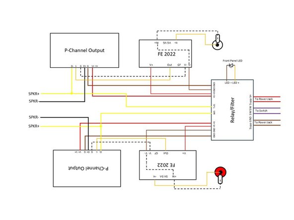
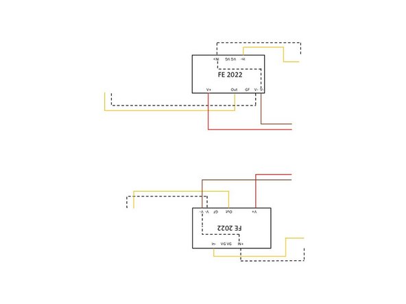
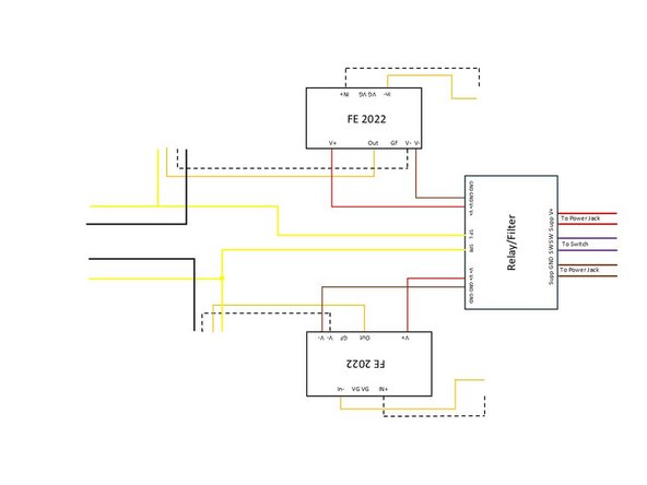
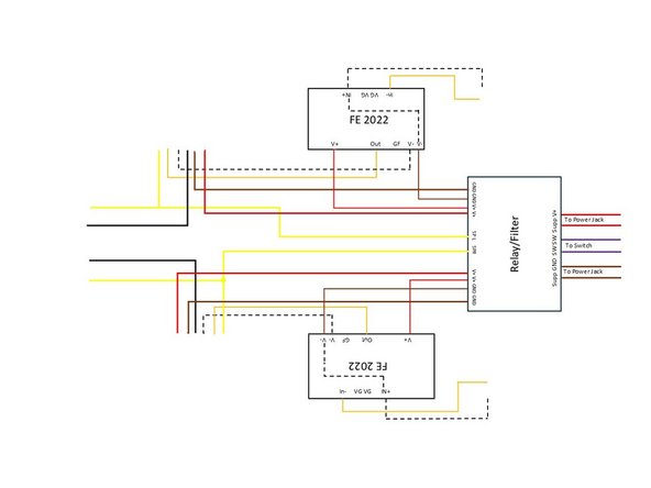
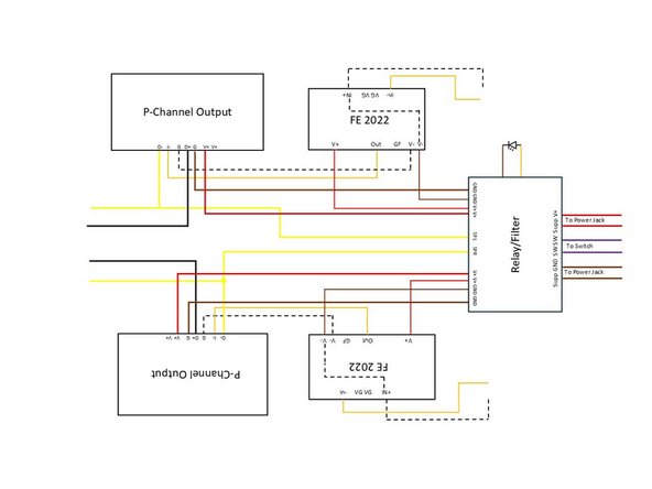
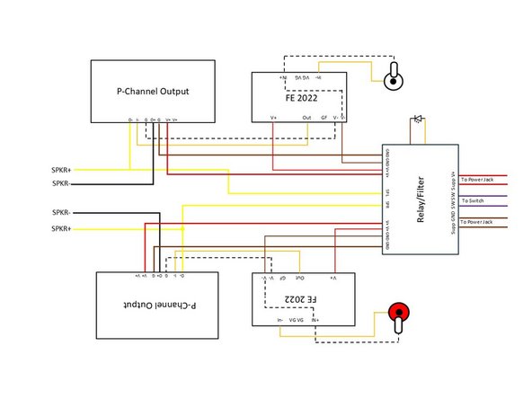
Image 1 - P-Channel wiring diagram. Colors are not representative of the build. Use this wiring diagram. The wiring diagram in the article has at least one wiring error.
-
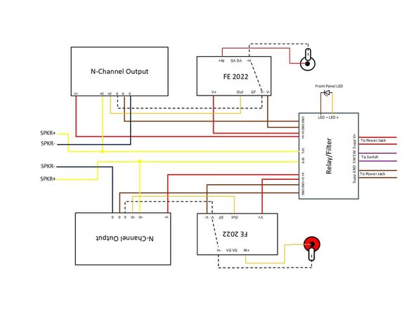
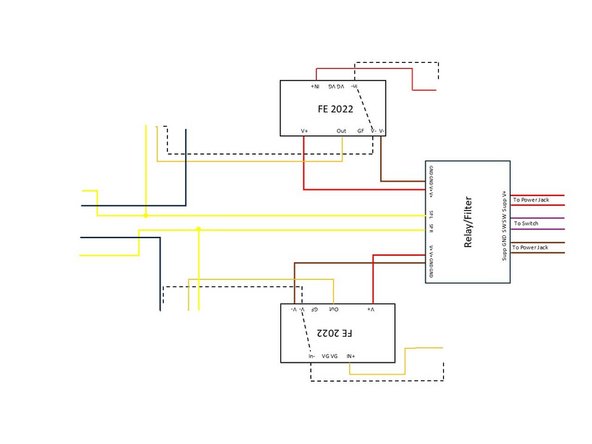
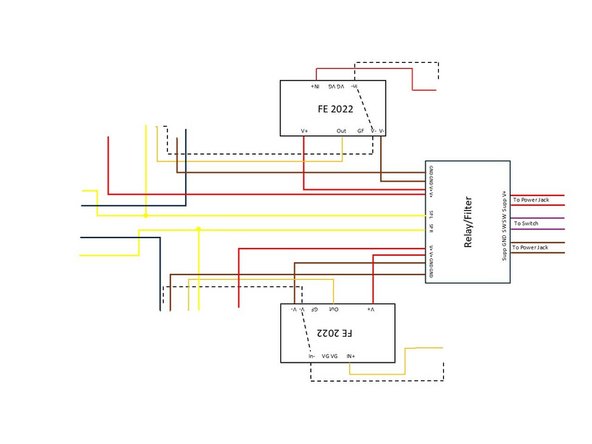
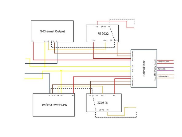
Image 2 - N-Channel wiring diagram. Colors are not representative of the build.
-
It is strongly recommended to print out the appropriate diagram and check off each wire as you build, particularly for newer builders.
-
-
-
THIS STEP IS FOR P-CHANNEL ONLY
-
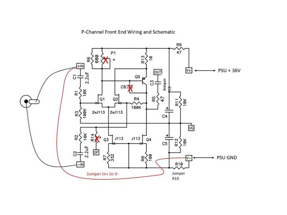
This wiring may seem odd at first, but if you've taken a look at the schematics and understand even a fraction of Nelson Pass' genius, there is a cool trick going on with this amplifier. It all starts with inverting the signal from the source to the front end. V- is GND in this circuit.
-
Image 1 - P-Channel Front End Schematic with notations for proper jumpers and input polarity.
-
-
-
THIS STEP IS FOR P-CHANNEL ONLY
-
This wiring may seem odd at first, but if you've taken a look at the schematics and understand even a fraction of Nelson Pass' genius, there is a cool trick going on with this amplifier. It all starts with inverting the signal from the source to the front end.
-
7 Inch lengths of thin wire were used for the input wiring (to the RCA jacks). 9 inch lengths of thin wire were used for the output wiring (to the output stage). 8 inch lengths of wire were used for the power wiring (to the PSU board).
-
A cordless drill is handy for twisting wires, but choose your favorite method.
-
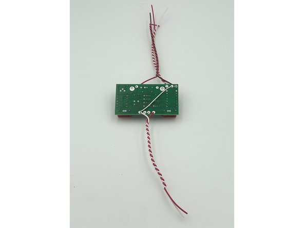
Photo 1 - Front of a board. It was properly cleaned after the photo.
-
Photo 2 - Back of a board. This photo is mainly to demonstrate the jumper from In+ to V-. Feel free to put the jumper on the front of the board if you prefer.
-
Wire your FE Boards as shown. Note - It does not matter which V- pads are shared.
-
Image 1 - Existing Wiring
-
-
-
THIS STEP IS FOR N-CHANNEL ONLY
-
The wiring is fairly straight forward. V- is GND in this circuit.
-
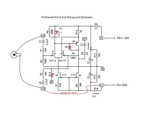
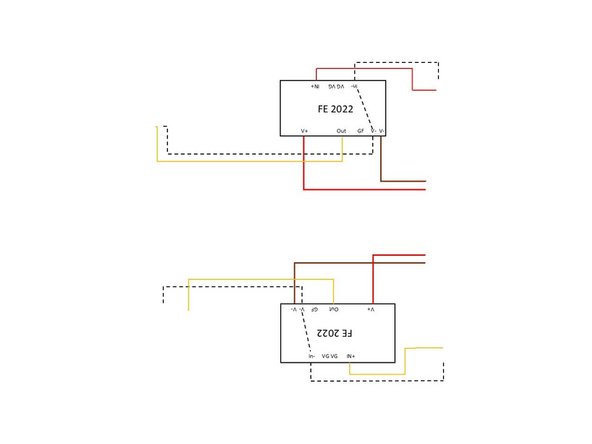
Image 1 - N-Channel Front End Schematic with notations for proper jumpers and input polarity.
-
-
-
THIS STEP IS FOR N-CHANNEL ONLY!
-
7 Inch lengths of thin wire were used for the input wiring (to the RCA jacks). 9 inch lengths of thin wire were used for the output wiring (to the output stage). 8 inch lengths of wire were used for the power wiring (to the PSU board).
-
A cordless drill is useful for twisting wires, but choose your favorite method.
-
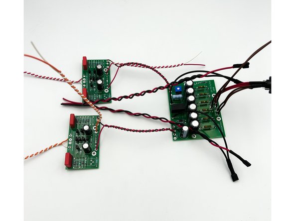
Photo 1 - Front of a board.
-
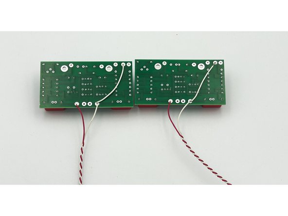
Photo 2 - Back of 2 boards. Note, this photo was taken before the output signal and DC supply wiring was added. It's mainly to demonstrate the jumper. Feel free to put the jumper on the front if that makes you more comfortable.
-
Wire your FE Boards as shown. Note - It does not matter which V- pads are shared.
-
Image 1 - Existing Wiring
-
-
-
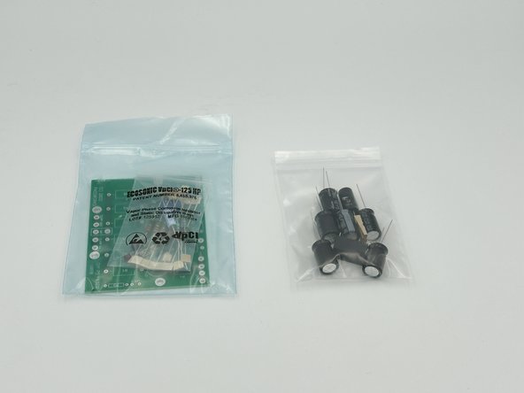
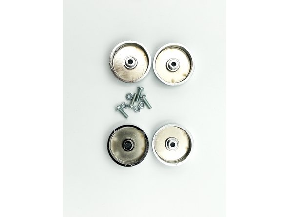
The benevolent DIY fairies included an additional PSU filter board and parts as shown in the photo. We recommend saving these for another project and using the parts shown in the following steps with your VFET amplifier.
-
Photo 1 - Parts you do not need for this build.
-
-
-
This board has two functions. Reduce turn on-off thump and filter the PSU. A control circuit delays the relay turn-on but quickly shorts the output of the source when the supply voltage starts to drop. P1 is used to adjust the sensitivity of the turn-off
-
Photo 1 - These are the parts you need for this step.
-
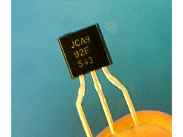
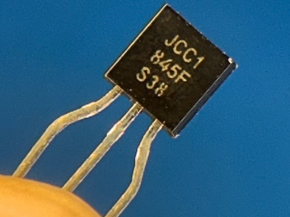
Make certain you identify and separate the PNP and NPN transistors. If you install them in the wrong locations, your amplifier will not work.
-
Photo 2 - PNP - Q1 - KSA992 (Apologies for the quality)
-
Photo 3 - NPN - Q2 - KSC1845
-
-
-
Do Not Install the LED Yet
-
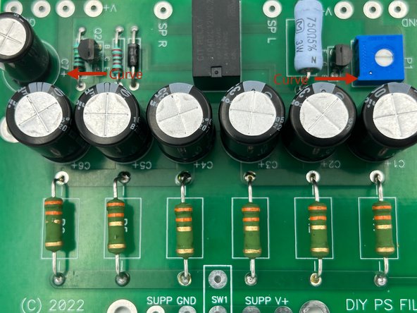
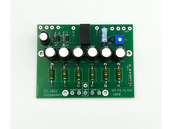
Stuff the boards per the schematics. A good sequence may be:
-
Small Resistors, Diode, and Potentiometer. The pot should be just fine at mid point.
-
Transistors. Again, ensure you have properly identified Q1 and Q2. Orient them properly!
-
Photo 1 - Transistor Orientation
-
Large resistors (raised a few mm off the board) and the Relay
-
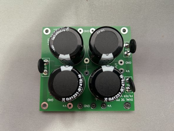
Caps
-
Photo 2 - Your board should look a lot like this.
-
-
-
2 x 4 Inch pieces of thick red wire and 2 x 4 Inch pieces of thick brown wire were used for wiring
-
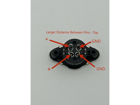
It is critical that you identify the positive and ground pins of the jack based on how it connects to the PSU. You can hook it to the PSU and measure, you can check the data sheet of the PSU, and/or you can follow exactly what was done here.
-
Photo 1 - The proper connection points.
-
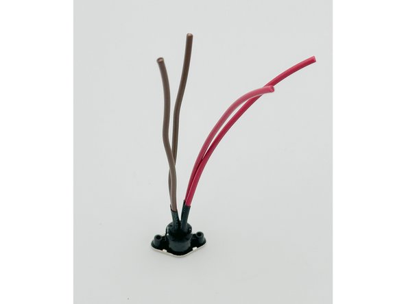
Wire the power inlet. Take particular care to not melt the jack. Pre-filling the solder cups and tinning each wire is helpful.
-
Photo 2 - It should look something like this. If you like, add a little shrink tubing to make you feel extra good that the pins won't short and to hide any joints you're not particularly proud of.
-
It is recommended that you connect the PSU, aka the "power brick", to ensure that you have +36V properly at the inlet. Do this carefully, and take care to not short the PSU. Don't touch the red to the brown with the PSU plugged in. The PSU will hold power in the capacitors for quite some time after it has been unplugged.
-
Twist the red wires together. Twist the brown wires together. Ensure the red and brown pairs are separated. Connect "crocodile clips" or equivalent to the red and brown pairs. Red DMM lead to Red and Black DMM lead to Brown. Ensure that there is no continuity (O.L. resistance) between the red and brown pairs. If not, STOP and fix your work.
-
Set your DMM to DCV. Make sure the PSU is not plugged into mains. Plug the PSU into the power inlet. Ensure you have +36V. If not, STOP and fix your work.
-
-
-
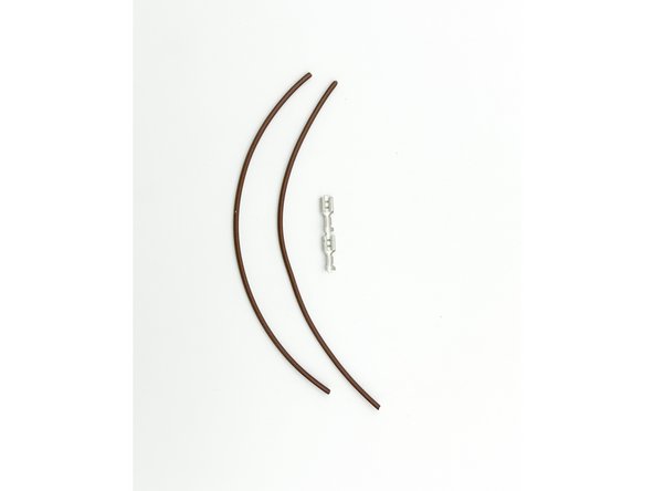
6" of the thick brown wire was used for the switch wiring.
-
Photo 1 - 2 x 6" lengths of thick brown wire and two small female Faston-type connectors.
-
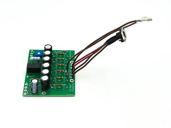
Terminate each switch wire and solder them to the Relay Filter Board.
-
Solder the Power Jack Assembly to the Relay / Filter Board.
-
Photo 2 - Your assembly should look something like this. It's nice to use heat-shrink tubing or covers for the female Fastons, but it's not necessary.
-
-
-
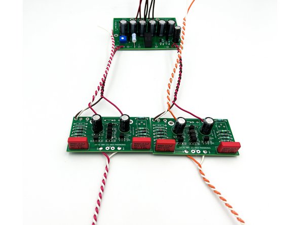
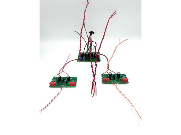
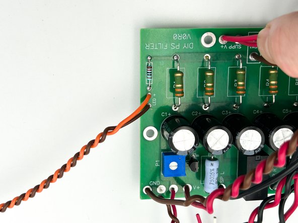
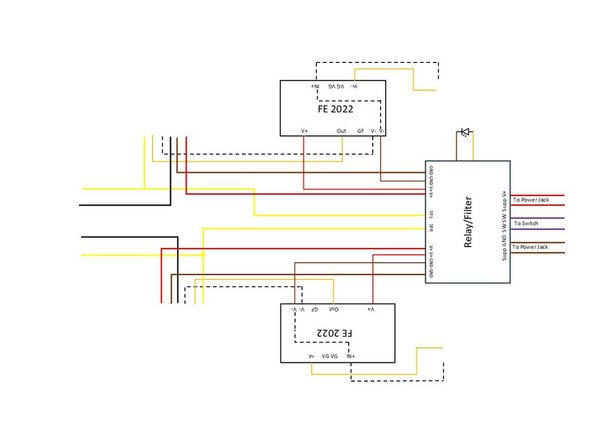
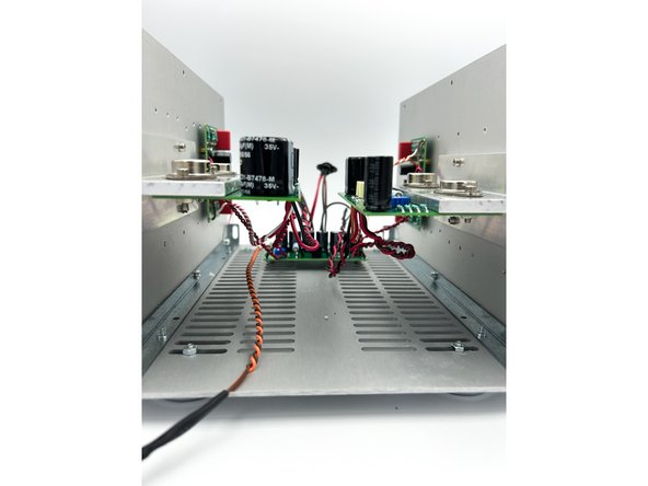
Solder the power wiring for the Front End Boards to the Relay/Filter board.
-
Photo 1 - Your Assembly should look a little like this.
-
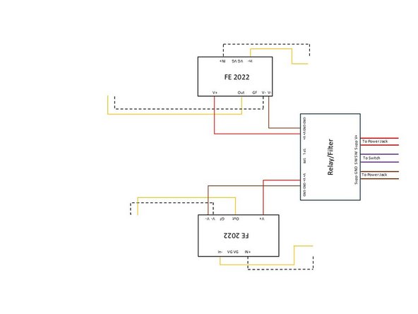
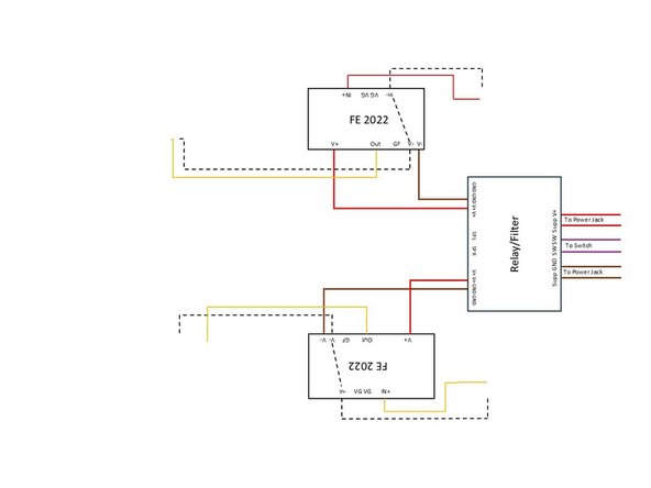
Image 1 - Existing Wiring - P channel.
-
Image 2 - Existing Wiring - N channel
-
-
-
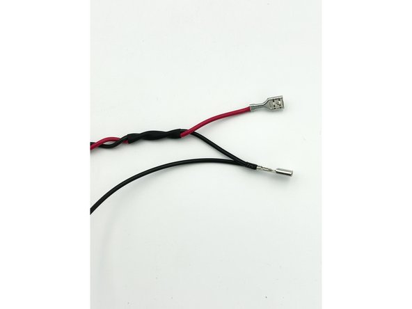
A 6" piece of thick black wire and a 12" twisted pair of black and red wire were used for this assembly.
-
If you have enough wire and/or are using your own wire, you may choose to reverse the colors based on preferences. Ultimately, the connection from the filter board / non-ground signal wire will connect to the "red" binding post in order to maintain the desired negative 2nd harmonic and maintain phase.
-
The 6" Black wire will connect to the Relay / Filter board. The twisted pair will connect to the output stage boards.
-
Note - The 'blue' crimp female Fast-On Type connectors included in the kit are not suitable for crimping only with the wire gauges included in the kit. It is strongly recommended to replace them with "red" crimp connections. Builders can strip away the blue insulation in order to crimp then solder as an option.
-
Photo 1 - The business end of the wire assembly.
-
Photo 2 - Full Assembly. Heatshrink tubing is very nice to have, but it is not strictly necessary.
-
Build two speaker wire assemblies
-
-
-
Solder the 6" speaker wires to the relay-filter board. SP L and SP R
-
Photo 1 - We're getting there. Once again, ignore the colors.
-
Image 1 - Existing Wiring. P-Channel
-
Image 2 - Existing Wiring. N-Channel
-
-
-
Create two 8" twisted pairs of thick wire and solder them to the Relay-Filter Board. V+ and GND.
-
Image 1 - Existing wiring: P-Channel.
-
Image 2 - Existing Wiring: N-Channel
-
Photo 1 - It may look something like this.
-
-
-
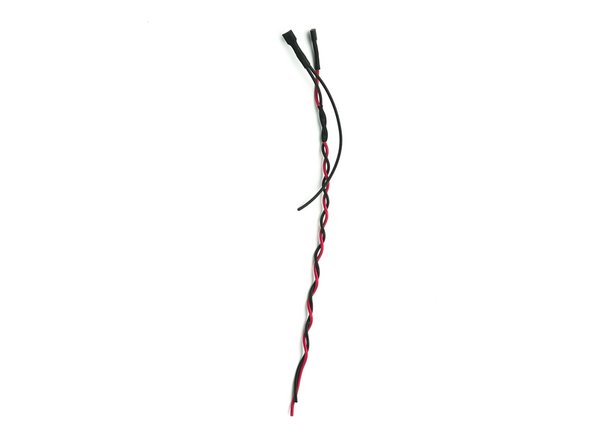
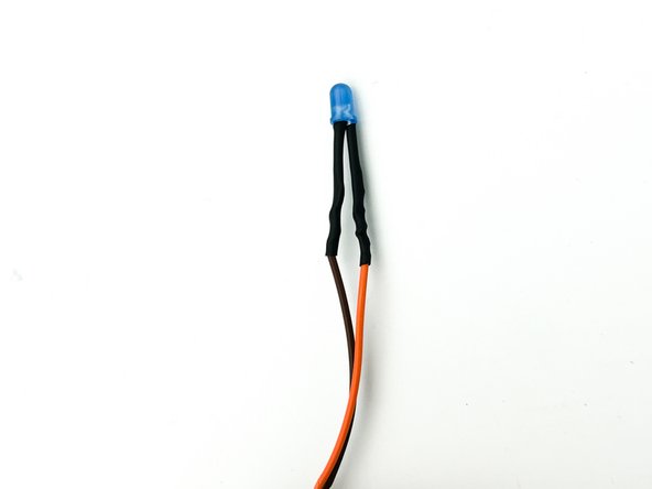
Create a 14" twisted pair of the thin wire.
-
Solder the LED to the wires: the long lead (+ Anode) and the short lead (- Cathode)
-
Photo 1 - A little heat-shrink tubing or a piece of wire insulation is excellent for ensuring that the leads do not short together and to add a bit of integrity to the assembly. The test builder still loves blue LEDs. The red LED in the kit is equally beautiful.
-
Solder the LED wires to the Filter-Relay Board. Ensure the polarity is correct. A quick diode check with a DMM is strongly recommended.
-
Photo 2 - Complete
-
Image 3 - Wiring so far. This is the P-Channel, but the LED wiring is exactly the same for the N-channel.
-
-
-
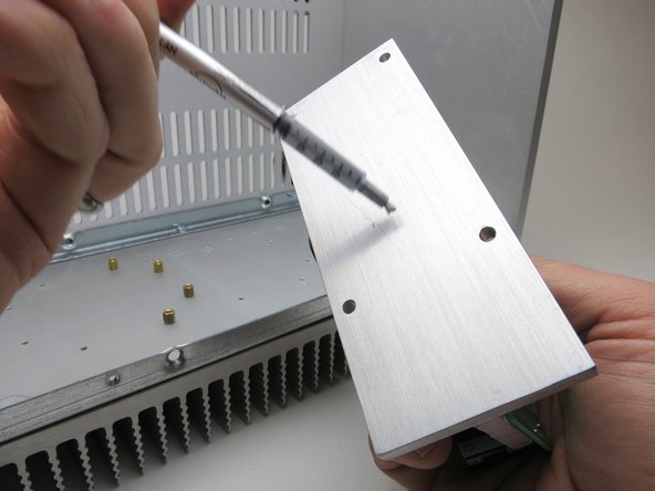
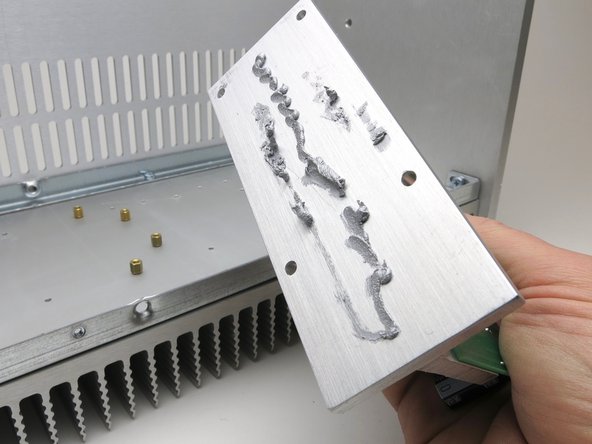
Peel the label from the syringe of thermal paste so you can monitor the volume. Empty 1/2 contents of the syringe onto each T-bracket.
-
Smear it all over. Try achieve a smooth even covering over the entire surface. Some users like to use a straight razor blade or a plastic spreader to even out the material.
-
This interface does not need to be electrically isolated. The thermal goop is electrically conductive, hence the metallic color. Be careful that you do not get it on your PCBs or other surfaces.
-
Photos 1-3 - Application and spreading sequence
-
Note - Photos conveniently borrowed from the 2021 VFET guide. Thank you @6L6!
-
-
-
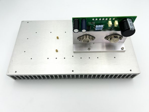
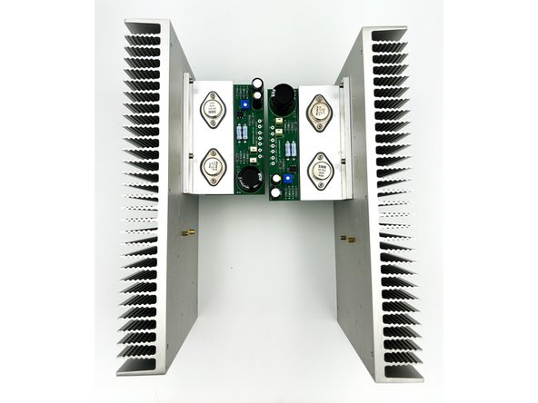
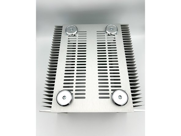
Attach both output stages to the heatsinks as shown using the longer M3 Allen Head Cap Screws and the "curvy" washers.
-
Install two brass standoffs as shown. Finger tight is perfectly fine.
-
Photos 1 and 2 - OS Mounted and standoffs installed.
-
You've now established the top, bottom, front, and back of the heatsinks.
-
-
-
Some photos were lost along the way, but the sequence is fairly simple. Two sets of brackets are included in the chassis box. You must ensure that you use the 4 pieces of the 'old' style brackets vs. the 'new' rectangular brackets.
-
Install the chassis rails to both heatsinks using the short M4 button head Phillips screws provided with the chassis.
-
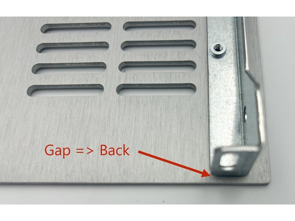
Temporarily install the bottom panel to the heatsinks with one or two screws. Check to see which end of the panel has a ~3mm overhang past the edge of the heatsinks. This side MUST go to the back of the chassis. If it does not. Turn the panel around. The back of the chassis is the end away from the output stage.
-
Photo 1 - Note the gap between the edge of the chassis rail (thus the heatsink) and the edge of the bottom panel. The gap must go to the back of the chassis.
-
Install the bottom panel to the heatsinks using the longer M3 cap head Allen screws provided with the chassis. Triple check that the gap / overhang is at the BACK of the chassis => on the opposite end of the output stage boards.
-
It is recommended to install the front panel now. You won't see the front panel installed for a few more steps (to make photos easier). Use 4x short M4 button head Phillips screws. The screws are the same type used for mounting the chassis rails.
-
Install the feet to the bottom panel. using the longer M4 button head Phillips screws and nuts provided with the chassis.
-
Photos 2 and 3 - Final framework with feet.
-
-
-
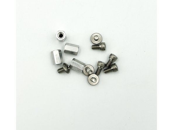
Parts Needed - 4 imperial button head screws, 4 standoffs, and 4 imperial (7/64" Allen head) cap head screws. These are in the VFET kit.
-
Loosely mount the standoffs to the bottom panel as shown in photo 1.
-
Some builders have found that installing the standoffs to the PCB first and then installing the board / standoff assembly to the bottom panel was easier. Poe-tae-toe : Poe-tah-toe.
-
Photo 1 - Mounting Location
-
-
-
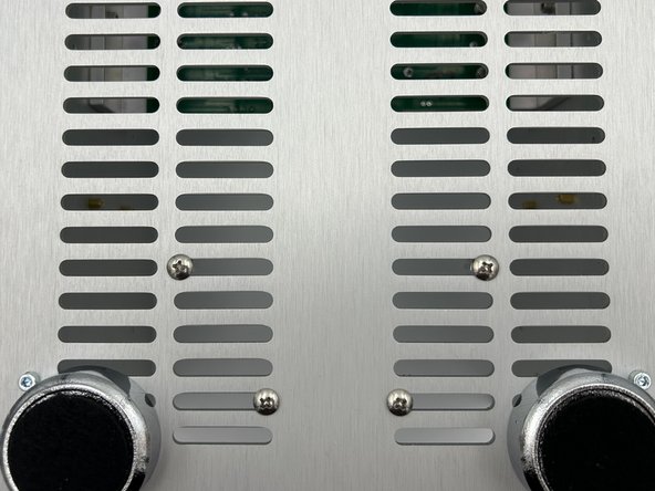
Mount the Filter-Relay board to the standoffs using the imperial allen-head cap screws. Tighten securely.
-
Mount the FE boards to the standoffs on the heatsinks using the short M3 allen-head cap screws.
-
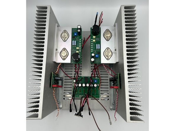
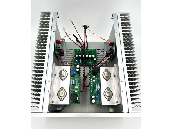
Photos 1 and 2 - It's starting to look like an amplifier.
-
-
-
If you have not done it already, install the front panel to the chassis rails using 4 x short M4 Phillips button head screws included with the chassis.
-
Make sure that you solder the wire pair connected to the filter relay board to 0- for the P-channel and O+ for the N-Channel. Consult the wiring diagram if there is any confusion.
-
Solder all connections to the output stage boards.
-
Photo 1 - Connections Soldered
-
Image 1 - Sooooo close! Existing Wiring: P-Channel
-
Image 2 - Sooooo close! Existing Wiring: N-Channel
-
-
-
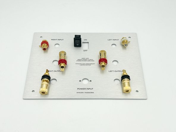
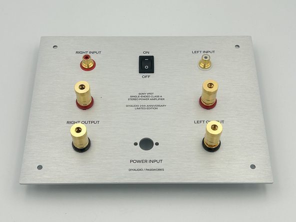
Photo 1 - Back Panel, input jacks, power switch, and binding posts.
-
The RCA jacks in the kits ship with the ground tab between the two plastic washers. The ground tab should be moved to between the interior plastic washer and the mounting nut, thus isolating it electrically from the chassis.
-
The power switch would be terribly hard to remove once installed. It is a very tight press-fit. ENSURE THAT YOU ORIENT THE POWER SWITCH PROPERLY.
-
You may find it easier to solder your input wiring if your orient the solder cups to face the top of the chassis and orient the ground tab toward the top of the chassis.
-
Install the input jacks, binding posts, and power switch onto the back panel.
-
Photo 2 - All components installed.
-
-
-
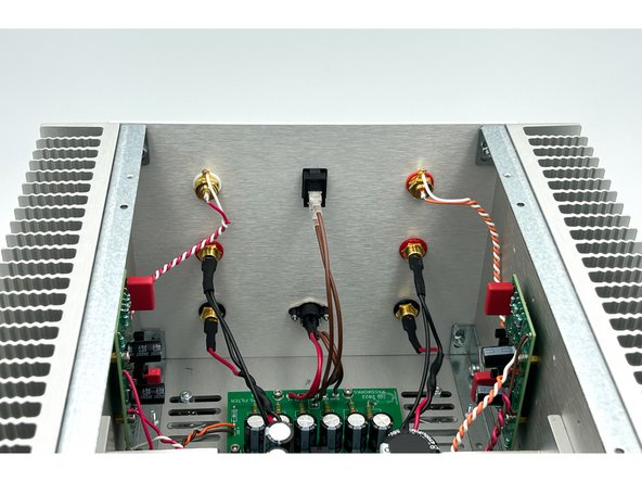
Install the back panel. Connect the binding posts. Connect the switch. Install the power jack.
-
Ensure that the wire from the filter board and its accompanying wire are connected to the RED binding post. This will maintain the proper phase relationship that Nelson Pass intends.
-
Solder your Input wires from the FE boards to the RCA jacks.
-
Photo 1 - All wiring Complete
-
Image 1 - Final Wiring: P channel
-
Image 2 - Final Wiring: N Channel
-
-
-
Triple Check Every Wire Using the Provided Wiring Diagram.
-
-
-
The OS boards come pre-tuned from Nelson Pass. Unless you are well-versed in distortion measurement, and/or want to try tuning both channels by ear, it is likely best to not turn the pots on the OS boards.
-
Prepare - place yourself in a position to quickly turn the power to the circuit on and off. Immediately power off the circuit if you smell smoke, see sparks, or if there is any indication that things are not working properly.
-
Connect the 36V DC 'power brick' to the amplifier and power on the amplifier.
-
You should hear the relay for the filter/relay board faintly click shortly after powering the circuit. If you do not hear the relay click, turn the pot fully CCW and then fully CW. If you do not hear the relay click, seek assistance. When turning from fully CCW to CW, leave the pot at the position when the relay clicks.
-
Check to ensure that you have <20mV of DC offset at the outputs. The output caps ensure no DC will reach your loudspeakers, but it doesn't hurt to check.
-
Check to ensure that you have roughly +36V at the V+ and GND for the filter relay board, the FE boards (remember GND is V-), and the output stage boards.
-
If you do not have proper voltages, or if the DC offset is suspect, troubleshoot or ask for assistance in the diyAudio forum.
-
For those that have the uncontrollable urge to play with their distortion profile, now would be an excellent time to note the voltage at the gate of the VFETs. If you're unsure, consult Nelson's article or perhaps wait.
-
-
-
If everything has gone well so far, connect your favorite test source and test speakers. Relax and listen to beautiful music.
-
If for any reason you do not hear beautiful undistorted music from both channels, please consult the experts in the diyAudio forums for assistance.
-
-
-
You've now completed your amplifier.
-


Congratulations on building the exceptional VFET amplifier.
A few things before you run off and start another project:
- This is a build guide by DIYers for DIYers. If you have any suggestions for improvement, notice any errors, or think something could be clarified, please post in the forums. Someone will be looking.
- Please post some pictures of your build in the forum. Nothing makes us happier than seeing completed builds and the creativity of DIYers around the world.
- Make sure to go to the forums and thank Nelson Pass for another amazing project.
- Last but not least, please click the button below if you completed the amp. It really helps the data dorks.
Cancel: I did not complete this guide.
One other person completed this guide.