
Introduction
What Are We Building?
This guide demonstrates the assembly and testing of a basic linear bipolar power supply of that will provide approximately +/- 24VDC under typical use conditions. It is rated for up to 2.5 Amperes per channel. This is a supply that might be used for First Watt amplifier designs sold through diyAudiostore.com. The supply can also be configured to suit a variety of amplifiers.
The kit can be purchased through the link below.
Simple Linear Bipolar Power Supply
All diyAudiostore.com kits require a level of knowledge and skill to assemble and operate, including knowledge of electronics, electricity, and electrical safety. DO NOT ATTEMPT TO ASSEMBLE THIS KIT IF YOU DO NOT POSSESS SUFFICIENT KNOWLEDGE OR SKILLS.
|
What Is Covered In The Guide?
This is a build 'guide'. It is not an instruction manual. The purpose is to assist in learning and guide DIYers with helpful information. Builders should not expect every detail to be covered.
|
It is not the only information needed to complete the project. Some additional links are included as guidance. It is critical to understand that the guide is intended to be a representation of how to complete the project. It is not the only way to complete the project. Builders that are unsure may want to begin with the assembly outlined in this guide, ensure that they have a working project, and then decide if they'd like modifications. It's DIY, choose your own adventure and have fun.
|
The project is considered moderately difficult. The guide is not intended to instruct someone through their first project. This guide is best suited to someone with an interest in audio electronics that has built one or two audio projects and needs a few helpful hints. Whether you are a first-time builder or have built 100s of projects, it is highly recommended to review this guide fully before beginning the build.
|
Builders should have a basic knowledge of electronics and should be proficient in through-hole PCB soldering. Although there are many helpful tips throughout the guide, before attempting to build this project, the builder should be confident in their ability to:
|
- SAFELY work with electronics powered with mains voltage,
- follow a schematic and identify the proper placement of parts from the schematic onto the PCB,
- understand basic measurements to identify parts correctly, and
- properly solder a variety of through-hole components.
|
What Else Do You Need?
The kit from diyAudiostore.com includes everything to stuff the boards using popular options. All builders will need appropriate hook-up wire, terminations to suit their build, an appropriate power transformer, and of course an amplifier.
|
Most importantly, if you have questions, please seek the help of a trained professional and/or your friends in the diyAudio forums.
Enjoy!!!
-
-
A black bullet is an instruction or valuable information.
-
Everything in this guide is important, but here's how you'll know something is REALLY important.
-
A green bullet is the mark to do something.
-
Warnings will be noted with a warning symbol and bold, red, underlined text. Pay Attention!
-
Tips and tricks and helpful reminders will be noted with an information bullet.
-
Photo / Image captions and information will be noted with the Photo/Image Icon.
-
-
-
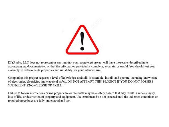
Click on the image to enlarge and read the warnings carefully.
-
Construction of this project requires working with potentially deadly mains voltage. In constructing this kit and following this guide, you agree to assume liability for any injury or damage resulting from exposing you or others to these voltages.
-
This project is intended to be used as part of a full assembly, including a proper enclosure. The builder must have or acquire the knowledge to construct an enclosure isolating mains voltage from unintentional contact.
-
-
-
If you do not possess the skills or knowledge necessary to safely complete this project, STOP! Seek assistance.
-
Never assume that shock hazards have been alleviated, even when the unit is not powered. Capacitors can store a lot of energy. DO NOT leave out the bleeder resistors. Never make contact with the PCB or the PSU assembly with any body part while the circuit is under power.
-
Before handling the PCB or any part of the PSU assembly, you MUST ensure that the circuit is de-energized, i.e. that the mains power is disconnected and that capacitors are discharged.
-
DO NOT use the PSU as an assembly in a project until it has passed all checks.
-
Use clip leads for your DMM as appropriate. Attach and remove the leads with the circuit de-energized when possible. Disconnect the mains power whenever it is not strictly required for testing.
-
Wear proper Personal Protective Equipment (PPE) including rubber-soled shoes and safety glasses. Work on a concrete or hardwood floor. DO NOT work around water or other liquids.
-
The thermistors used for inrush current limiting will get VERY hot in normal use. DO NOT TOUCH them until it is verified that they have cooled to ambient temperature!
-
-
-
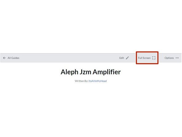
Your first "real" black bullet. You may notice that you have the option to view in "Full Screen". I like it either way, but I prefer full screen. This web platform works well with tablets too. I've tested it with various monitors of various aspect ratios and tablets. Choose what looks best to you. The printed .pdf format is nice too.
-
Image 1 - If you don't know how to get to "Full screen", take note of the box around "Full screen" at the top of the guide above the header / title. That's where you click to move to Full Screen.
-
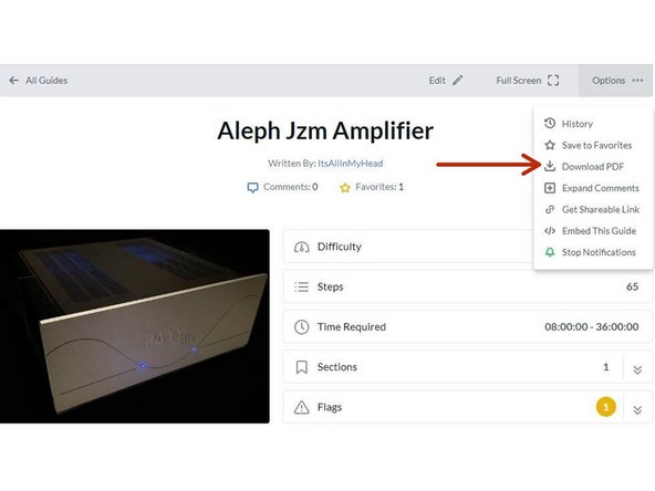
Image 2 - If you don't know how to print the document. Note that you can download this guide as a .pdf and print it.
-
In all the on-line views, if there are multiple images and/or photos within a step, mouse-over or tap/click as appropriate to make which ever one you'd like the primary image (the biggest one).
-
Mousing over / tapping on the primary image will change the cursor to a magnifying glass. Clicking / double tapping will open a new tab or enlarge and center the image on your screen.
-
In full-screen mode, the keyboard right and left arrows or clicking the arrows in the upper right will advance or reverse one step.
-
Your first "real" green bullet. Choose if you want to view in full screen or standard (if you haven't already) and/or print a copy of the guide.
-
Get started. Move on to step 5.
-
-
-
All mistakes are preventable, and this guide moves slowly through each step.
-
The most common issues with builds are mis-stuffed parts and poor solder joints.
-
Symptoms from mis-stuffed parts typically manifest quickly. For this build, pay particular attention to the LEDs and the capacitors. The impact from an improper part placement can be benign, or you could release the "magic smoke".
-
The impact of poor soldering varies. A short/bridge that will impact your build is unlikely, but can be catastrophic. More commonly, the issues are partial coverage or a cold joint. Symptoms may not manifest until you least expect them, and they may be intermittent. Inspect each and every joint under magnification. You'll be glad you did.
-
DMM issues can lead to frustration.
-
Check the batteries. When in doubt, replace the batteries.
-
Make sure your probes are reading "0 Ohms" resistance probe to probe or are appropriately compensated.
-
Make sure your probes are connected properly. For this guide, the polarity of the voltage being read is critical; so always observe and report polarity.
-
-
-
The notation of voltages requiring a decimal place will have a "V" in place of the decimal. 24V5 is 24.5 Volts or 24,5 Volts.
-
The notation of resistance requiring a decimal place will have a "R" in place of the decimal. 0R5 is 0.5 Ohms or 0,5 Ohms.
-
The notation of Amperage requiring a decimal place will have an "A" in place of the decimal. 1A1 is 1.1 or 1,1 Amperes.
-
There are a number of common standard mains voltages worldwide. 110, 115, and 120VAC will collectively be referred to as 115VAC. 220, 230, and 240VAC will collectively be referred to as 230VAC.
-
-
-
The most common action you'll take throughout the guide is to "install" your parts AKA stuff the PCB. Parts installation includes:
-
Ensuring you have the correct parts to match the PCB silkscreen / schematic.
-
Ensuring the leads are bent to the proper pitch (if applicable).
-
Soldering the parts into place.
-
Cutting the leads to the proper length*
-
It is also acceptable to clip the leads to the correct length prior to soldering. There are compelling reasons to do it either way. If you are unsure, watch a few videos, read a few articles, and do some test soldering of your own to see what works best for you. If you choose to clip prior to soldering, use the correct tool.
-
Cleaning and inspecting the joint. It is strongly recommended to use magnification and good lighting to inspect each and every joint.
-
-
-
This guide does not cover how to solder / install through hole parts. There are a variety of great ways to install a part and achieve a proper solder joint, but there are common themes throughout. Below are a few links. See what works best for you. Neither diyAudio nor the author have any affiliation with any of the companies or persons linked.
-
-
-
-
-
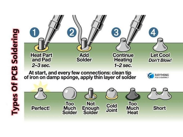
Image 1 - A basic soldering sequence and examples of both good and poor joints. Taken from the Rayming PCB & Assembly Guide linked above.
-
The key variables to soldering are the type of solder chosen, the tip used, and the tip temperature. These all vary widely between users and are inter-related. If you are new to electronics, the best solution is practice. Scrap electronics and inexpensive parts are a wonderful way to learn.
-
Leaving the iron tip on the joint for longer than around 5 seconds is not a substitute for too small an iron tip or too low a temperature. If you need to reflow a joint, or if the solder isn't flowing, flux is your friend.
-
-
-
The builder must ensure proper terminations for safe and trouble-free operation.
-
It is often discussed whether to solder and/or crimp or whether spade-type connections are appropriate for this application. In the author's opinion, a properly-crimped connection using high quality terminations and a proper crimper is an excellent choice. Adding a bit of solder can't hurt, but it will never "fix" an improper crimp.
-
The advantage is that many crimped terminations allow flexibility.
-
The disadvantage is that a proper crimp is only achievable when using a proper tool along with good hardware.
-
Unfortunately, many people don't have a proper crimper for each type of termination, and there is a lot of terrible hardware on the market. Consult your friends in the forum for some recommendations that fit your choice of termination and your budget.
-
The video linked does an excellent job of demonstrating various crimps. You are strongly encouraged to watch it. Excellent Crimping Video. Note - Neither the author nor DIYAudio have any affiliation with the video's creator.
-
-
-
Plan your build. Read this guide a few times before you even take the first part out of the bag.
-
Go slowly. You're not getting paid to do 100 boards a day. This should be relaxing and fun. A lot of errors can be traced back to lack of attention and rushing.
-
The ONLY parts within reach should be for the step you are working on at the moment. Many parts look very similar.
-
Move the boards and your body around to give yourself the best angle to solder each part. Get close to your work and use magnification. A well-lit workspace is important. You don't stand a chance if you can't see.
-
Before moving to the next part, triple check your work. Hopefully you won't make any errors, but it is much easier to remove one part than many to fix an error. Using the included documents and following a basic sequence will assist with error-free construction.
-
Take plenty of breaks and stop at any point confusion or frustration sets in. There are a few recommended stopping points throughout the guide, but stop any time you mentally or physically need to recharge.
-
Try to keep distractions to a minimum.
-
Neatness counts!!! Take pride in your work. You'll be happy you did.
-
-
-
Print a copy of each of the relevant documents found at the end of this guide or in the Documents Tab if you are viewing in Full-Screen Mode. You'll need to go back to the Introduction (full-screen mode) or scroll to the end of the guide to find the documents / documents tab.
-
Tidy up your workspace. Keep in mind that you'll be working with a very hot soldering iron, and it can be easy to misplace parts. A few recomemndations:
-
No other parts for any other projects should be within arm's reach.
-
The floor and the area around the workspace should be clean, just in case a part escapes.
-
-
-
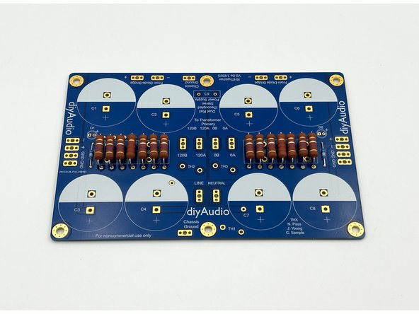
Look over your boards and get familiar with the parts placement. Compare a board to the parts placement document.
-
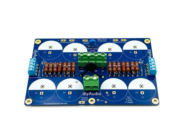
Image 1 - Front view of the PCB.
-
You will not stuff every component. The PCBs include options for various power supply configurations.
-
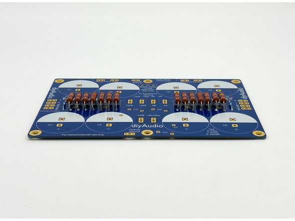
Image 2 - Back view of the PCB, sometimes referred to as the solder side. There are options for installing some of the terminal blocks on the back of the PCB depending on your personal choice for layout.
-
Main PCB Dimensions - 170mm x 112mm +/- 0.02mm
-
Rectifier / Snubber PCB Dimensions - 30mm x 39mm +/- 0.02mm
-
-
-
There are a number of options for builders. This is a very versatile PCB.
-
If you already have a project for which the PSU will be used, it is strongly advised to determine your initial layout. This will allow you to choose mounting options and terminations.
-
Note your mains voltage. You should have either 115VAC mains or 230VAC mains. This is not a regulated power supply. So, fluctuations in mains voltage will affect the output voltage. It is critical to build the power supply in accordance with your mains voltage and your transformer configuration.
-
The kit from diyAudiostore.com comes with terminal blocks to connect mains wiring and the transformer primaries along with the amplifier boards. The board will also accept standard male spades, or you can solder the wiring directly.
-
Determine the orientation of the PSU in the chassis and where the transformer will sit relative to the PSU along with your expected wire routing. Choose whether you would like to mount any connections on the bottom of the board.
-
The author likes the mains connections and transformer primary connections on the bottom of the board in some situations. It makes for a clean look and tidy wire routing.
-
-
-
Open the bags of parts, verify them against your packing list and get to know what they look like.
-
Place all of your parts carefully in a bowl or somewhere they will not get lost, knocked onto the floor, accidentally spread around your workbench, or mixed in with other parts not associated with this project.
-
Many people like to separate their parts by type. For this project, it's not necessary, but choose whatever method works best for you. It's fairly simple to keep all the parts together and select only what is required for a particular step.
-
-
-
Tidy up your workspace. Keep in mind that you'll be working with a very hot soldering iron, and it can be easy to misplace parts.
-
Clean both sides of the boards with isopropyl alcohol or your favorite PCB cleaner. A dust and oil free board helps the solder to flow nicely. Plus, they're very pretty. Yes, that's real gold.
-
-
-
There are only two types of resistors and 3 values. If you are building a +- 24V PSU, appropriate LED current limiting resistors are included with the kit. If you are using different voltages and/or like your LEDs at a specific brightness, feel free to use your own, or none at all.
-
(Optional) Install R15 and R16, the LED current limiting resistors.
-
The 3W filter resistors will get quite warm. Mounting them a few mm above the board allows better air flow. The bleeder resistor should not get hot, but it looks nice when they are mounted at the same height.
-
Install R7 and R14, the 2k2 bleeder resistors.
-
Install R1-R6 and R8-R13, the 0R47 filter resistors.
-
Photo 1 - Resistors installed.
-
Photo 2 - Elevated 3W resistors.
-
-
-
Based on your desires, LEDs can be installed on the main PCB and/or you can attach wires to use them as front panel power indicators. They're completely optional.
-
The "flat" side of the LED is indicated on the silkscreen noting the negative side of the LED, the cathode. There is also a (+) on the PCB noting the positive side of the LED, the anode. Do not use the pad shape as a polarity designator.
-
The LEDs included in the kit do not have a flat edge. The longer of the two leads is the positive lead, the anode.
-
(Optional) Install the LEDs or LED wiring according to your build plan.
-
-
-
Install C9 - This is a safety-rated cap for spark suppression at turn-on.
-
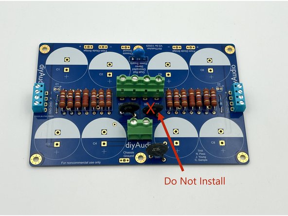
Do Not Install TH2 or TH3 at this time!
-
(Optional) Install TH1 (ground lift). TH1 is marked CL-60. For all First Watt amplifier projects sold through diyAudiostore.com, the ground lift is recommended. If you unsure, seek the advice of the circuit designer for your amplifier.
-
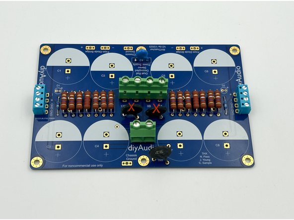
(Optional) Install the blue terminal blocks. They can be installed on the top or bottom of the board based on the build plan. They come attached in pairs in the kit. If they happen to slide, simply press them until they are level. You may also choose to direct solder wiring or use typical male spades.
-
(Optional) Install the green terminal blocks. Simply slide the pair together for the transformer primary connections. These can be installed on the top or the bottom of the PCB based on build plans. You may also choose to direct solder wiring or use typical male spades.
-
Photo 1 - DC Terminal Blocks (Blue), Mains and Transformer Primary Terminal Blocks (Green) installed on the top of the board. Builders with limited chassis height may choose this configuration.
-
Photo 2 - Mains and transformer primary terminal blocks installed on the bottom of the board. This allows easier access (particularly to the transformer primary wiring). It also allows slightly better wire routing in a lot of circumstances.
-
-
-
If you unfamiliar with your transformer, please skip ahead to step 29 before installing TH2 / TH3
-
You should clearly know:
-
Mains Voltage at the location where the PSU will be used: 115V or 230V
-
If the transformer has a single primary or dual primary windings
-
If the transformer secondary output voltage is determined by 115V or 230V mains connected to the primary winding(s).
-
If you are not 100% certain about any of those parameters. STOP! Seek assistance. DO NOT GUESS!
-
-
-
For 115V Mains and a transformer with a single 115V primary; proceed to step 21
-
For 115V Mains and a transformer with dual 115V primaries; proceed to step 22
-
For 230V Mains and a transformer with a single 230V primary; proceed to step 23
-
For 230V Mains and a transformer with dual 115V primaries; proceed to step 24
-
-
-
This step applies to 115V mains using a transformer with a single 115V primary
-
Install TH2 - Double check the part marking. It should read "MS22"
-
Reminder - The thermistors used for inrush current limiting will get VERY hot in normal use. DO NOT TOUCH them until it is verified that they have cooled to ambient temperature!
-
Do not install TH3
-
Photo 1 - Install TH2. Do not install TH3
-
Skip to Step 25
-
-
-
This step applies to 115V mains using a transformer with a dual 115V primaries
-
Install TH2 and TH3. Double check the part marking. It should read "MS22"
-
Reminder - The thermistors used for inrush current limiting will get VERY hot in normal use. DO NOT TOUCH them until it is verified that they have cooled to ambient temperature!
-
Photo 1 - TH2 and TH3 Installed
-
Skip to Step 25
-
-
-
This step applies to 230V mains using a transformer with a single 230V primary
-
Install TH2. Double check the part marking. It should read "MS22"
-
Do not install TH3
-
Reminder - The thermistors used for inrush current limiting will get VERY hot in normal use. DO NOT TOUCH them until it is verified that they have cooled to ambient temperature!
-
Photo 1 - Install TH2. Do not install TH3
-
Skip to Step 25
-
-
-
This step applies to 230V mains using a transformer with a dual 115V primaries
-
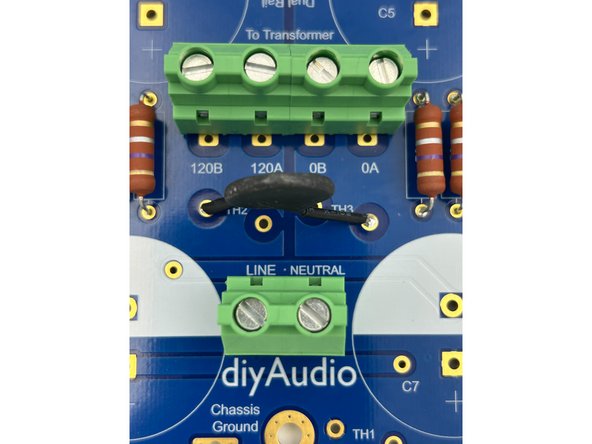
Install a single thermistor across the outer pads for TH2 and TH3. Use a small piece of high-temperature rated heatshrink tubing or a piece of wire insulation on the bare portion of each leg to ensure the legs cannot short against adjacent pads. Double check the part marking. It should read "MS22".
-
Reminder - The thermistors used for inrush current limiting will get VERY hot in normal use. DO NOT TOUCH them until it is verified that they have cooled to ambient temperature!
-
Photo 1 and 2 - Thermistor installed across the outer pads for TH2 and TH3
-
-
-
Verify the orientation of the electrolytic capacitors! The negative side is indicated with a band. The band aligns with the filled, white side of the silkscreen.
-
The capacitors provided in the kits snap in. Simply align the tips of the leads with the holes, give them a gentle press, and give them a slight twist to lock them into place. They also need to be soldered to the pads. The leads do not need to be clipped.
-
Install C1-C8.
-
Photo 1 - Capacitor orientation
-
Photo 2 - Main PCB Complete.
-
-
-
These boards provide an all-in-one solution for the rectifiers and snubbers. The snubber resistor value is unique to the transformer and how it is wired. The diyAudiostore.com kits come with proper resistors for two common transformers configured for typical US mains. Kits may be updated with other popular transformers / configurations.
-
A snubber circuit is not necessary for the operation of the PSU. If the kit does not contain the Rs value for your transformer / mains configuration, or if you don't know the value, it can always be installed later. Simply mount the rectifiers in your chassis without the circuit boards and save them for later.
-
The 12Ohm resistor is appropriate for an Antek AS-3218 wired for 115V mains. The 16.9Ohm resistor is appropriate for an Antek AS-4218 wired for 115V mains.
-
For other transformers, or if you are configuring for 230V mains, the appropriate value may be found in the Quasimodo Results Thread
-
Install the snubber resistors and the film caps.
-
Install the rectifiers. A wide chisel tip is useful.
-
Photo 1 - Completed boards. You can write the value of the snubber resistor on the board if you like.
-
-
-
It is highly advised to use a variable transformer and/or a dim bulb tester (DBT) for the initial testing of your power supply. This guide will demonstrate the use of both.
-
For testing an unloaded power supply, a simple dim bulb tester may prevent catastrophic failure and is strongly recommended. If you are unfamiliar with DBTs, seek assistance. It is out of scope for this guide.
-
A variable transformer is also nice to have to slowly ramp up the voltage and observe the behavior of the circuit.
-
Wiring and testing your power supply requires working with potentially deadly mains voltage. If you do not possess the skills or knowledge necessary to safely complete this project, STOP! Seek assistance and work under the supervision of a qualified electrician / technician.
-
Never assume that shock hazards have been alleviated, even when the unit is not powered. Take caution and ensure capacitors are discharged as appropriate.
-
Use clip leads for your DMM as appropriate. Attach and remove the leads with the circuit de-energized when possible. Disconnect the mains power whenever it is not strictly required for testing.
-
Wear proper Personal Protective Equipment (PPE) including rubber-soled shoes and safety glasses. Work on a concrete or hardwood floor. DO NOT work around water or other liquids.
-
-
-
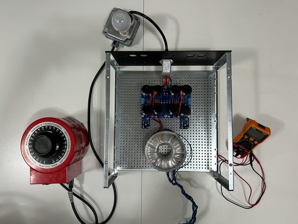
When practical, it is convenient to test the power supply using the chassis / baseplates you will use for your amplifier build. It is a safe mounting platform and allows a check of layout and wire routing.
-
This guide uses the baseplate, and back panel supplied with the 400mm diyAudio Deluxe chassis along with the PEM supplied with the back panel parts kit.
-
The power supply is versatile in both the type of terminations used and their placement. Below are the choices demonstrated:
-
The DC voltage target will be approximately 24VDC under load, so approximately 26VDC unloaded. The Antek AS-4218 was chosen for the transformer. If you're unsure what transformer is appropriate for your amplifier project, seek guidance.
-
The low voltage AC wiring from the transformer secondaries will be connected on the bottom of the board using terminal blocks supplied with the kit. The DC terminals are placed on top of the board using the terminal blocks supplied with the kit.
-
Wiring from the main board to the rectifiers is soldered to the PCB and terminated properly with female spade connections for connection to the rectifiers. Transformer secondaries are properly terminated with female spades for connection to the rectifiers.
-
The transformer shield is terminated with a standard ring lug for connection to the chassis baseplate / mains earth.
-
LEDs are installed on the PCBs. The current limiting resistor from the kit is installed and is appropriate for 24V at a nice brightness level.
-
-
-
This guide is not intended to explain everything there is to know about a transformer. It does not cover windings ratios, current ratings, efficiency, sag, loading, or other factors. It provides basic information about two transformers commonly used to construct a bipolar 24VDC PSU used for First Watt style amplifiers.
-
If you are unsure of anything, seek guidance in the forums and/or from a trained professional.
-
When wired properly, the 'input' to the transformer is mains voltage (115VAC or 230VAC) and the output is "stepped down" to approximately 18VAC when under a typical load.
-
The transformer shown is a common choice for a First Watt style amplifier; Antek's AS-4218. The datasheet is included in the files for reference. The datasheet for a Toroidy TS400 Series transformer is also provided as a reference. Always check the datasheet for your specific transformer!
-
It is critical to identify the mains voltage designated for the transformer. The Antek transformer can be used for both 115V and and 230V mains. The Toroidy is only suitable for 230V mains.
-
It is critical to identify and separate all of the wires for your transformer. Transformers used for this project must be dual secondary, i.e., there must be two secondaries supplying identical AC voltage.
-
-
-
The Antek AS-4218 is a dual primary transformer. It can be used for both 115VAC input and 230VAC input when wired appropriately. Antek's codes are fairly simple. S is for Shielded. 4 is 400VA. 2 is dual secondary. 18 is the secondary voltage.
-
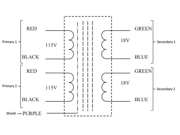
Image 1 - Primary windings in parallel when used for 115 VAC mains voltage.
-
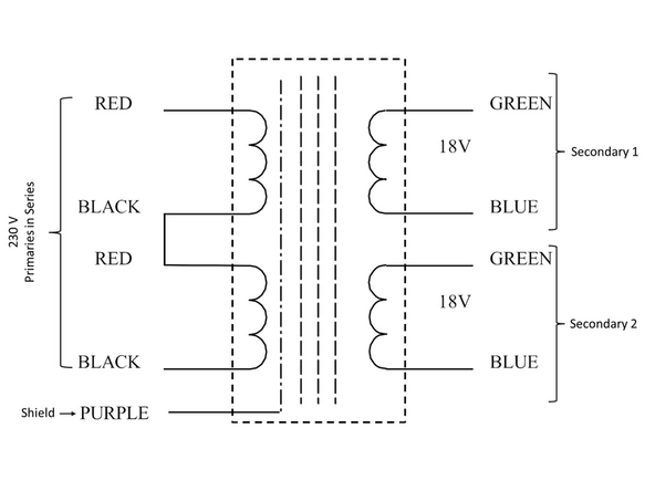
Image 2 - Primary windings in series when used for 230VAC mains. Connecting the primaries in series effectively creates a single primary. This works because the input voltage is doubled from 115V, and therefore the resulting winding ratio results in the same 18VAC output.
-
-
-
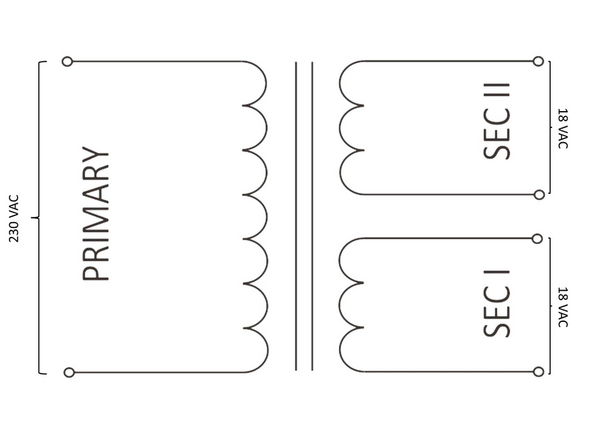
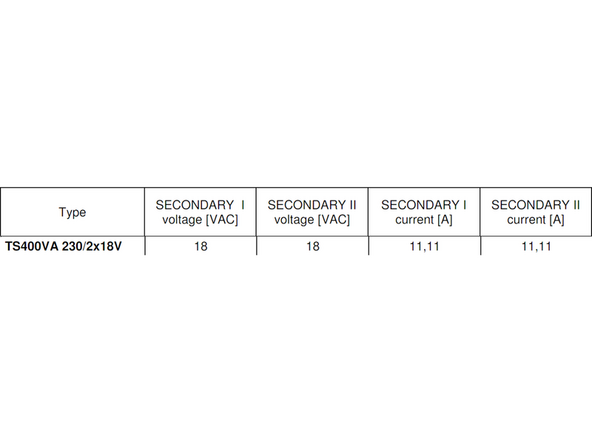
Toroidy transformers are popular in countries with 230VAC mains. The Toroidy TS-400 series transformers are a single primary. They are only suitable (unless custom ordered) for 230VAC mains.
-
Image 1 - Basic Schematic of the single primary / dual secondary transformer with 230VAC input and 18VAC output on each secondary
-
Image 2 - Toroidy's identification system is fairly straight forward. 400VA - 230V primary and 2 x 18 V secondaries.
-
-
-
It is fairly simple to identify transformer primaries and secondaries. All that is needed is the datasheet and a DMM. The datasheet for the Antek AS-4218 shows that each primary is a red/black pair; each secondary is a green/blue pair, and the shield is purple.
-
There is rarely consistency among manufacturers for color coding. Manufacturers may use different color coding across models and/or may change their coding over time. Ensure you check the specifications and/or the markings on the transformer itself.
-
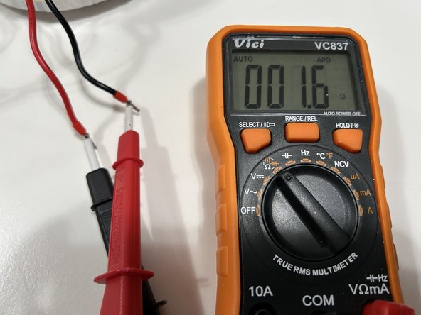
With a DMM set to continuity or resistance, identify which pairs are two ends of the same wire. Separate them, and label them. The primaries will have a resistance typically of a few Ohms. The secondaries will have a resistance typically below 1 Ohm.
-
Photo 1 - Two ends of the same primary winding. Low resistance. They should be paired and labeled.
-
Photo 2 - Two ends of the same secondary winding. Low resistance. They should be paired and labeled.
-
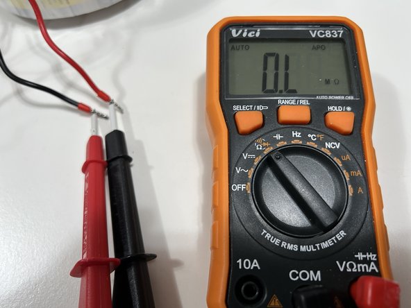
Photo 3 - These are not two ends of the same primary winding. Note that the resistance is over limit. They should not be paired.
-
If you haven't done so already, terminate the primaries, secondaries, and the shield as you see fit. It might be wise to not cut the leads until the layout is fully checked. It may cost you a few terminations, but cutting the wiring too short is never a fun thing.
-
Note - DO NOT use bare stranded wire or tinned stranded wire in combination with screw-down terminal blocks.
-
-
-
Check the initial layout and plan wire routing as appropriate.
-
The main goals are to ensure clearance around all boards, keep AC and DC wiring as short as practical, and to place the toroid as far away as practical from signal wiring.
-
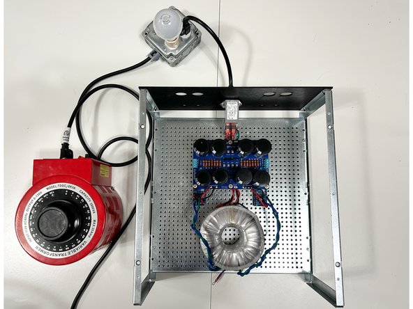
Photo 1 - This layout should work nicely for many amplifiers. Note - nothing is permanently fixed and the transformer wiring has been left at full length. It can be cut to length (optional) once the layout is finalized.
-
-
-
Install the mains AC wiring. In the USA, it is common to use black for 'live', white for neutral, and green or green with a yellow stripe for mains earth. Use whatever is common in your area and that you can easily recognize.
-
It is critical to use proper terminations and to ensure that the mains earth is connected securely to the chassis base plate. No other wiring should share the mains earth to chassis connection.
-
Photo 1 - For mains AC wiring, 16AWG stranded wire was used along with female spades properly sized for the PEM and wiring. A ring termination was used for mains earth chassis connection. Bootlace ferrules were used for live and neutral to connect to the terminal blocks on the main board. Links to all tools are provided in the tools section.
-
Note - DO NOT use bare stranded wire or tinned stranded wire in combination with screw-down terminal blocks.
-
-
-
If you have not already, install wiring to connect the main PCBs to the rectifiers.
-
16AWG stranded wiring is a popular choice. Appropriately sized female spade connectors or wiring soldered directly to the rectifiers are common choices.
-
Photo 1 - The wiring for connecting the rectifiers to the PCBs is at these points noted as "From Diode Bridge". Red is commonly used for V+, and Black is common for V-, but use anything that is easily recognizable.
-
-
-
Securely connect your AC Mains live and neutral wiring to the main PCB.
-
Photo 1 - It may be helpful to transfer markings for the Live and Neutral noted on the top of the PCB to the bottom of the PCB.
-
-
-
Ensure you check the reference image to ensure your transformer primaries are connected properly!
-
It is critical to have the transformer primaries properly identified and separated for dual primary transformers.
-
Image 1 - Proper connections for a dual primary transformer.
-
Securely connect your transformer primaries.
-
-
-
Ensure you check the reference images to ensure your transformer primaries are connected properly!
-
Image 1 - Proper connections for a single primary transformer.
-
Securely connect your transformer primary.
-
-
-
The rectifiers should be secured to the chassis floor or heatsinks. The rectifiers should not be connected to the main PCBs or to the transformer secondaries at this point. The transformer does not need to be secured, and it is not necessary to connect the shield wire.
-
The main boards should be fastened securely to the baseplate / chassis floor using conductive standoffs. Note - it is optional to connect the main board to the chassis with wire if conductive standoffs are not used.
-
Ensure that the mains earth wire from the PEM is secure to the chassis floor. Check that there is no more than a fraction of an Ohm resistance between mains earth at the PEM to all components of the chassis and to the pads marked chassis gnd on the main PCB.
-
Ensure that both transformer secondary windings are terminated properly and/or cannot make unintentional contact with any other wiring or the chassis.
-
Tidy the workspace and ensure you can reach the primary power switch quickly without obstructions. If you need to switch something quickly, you don't want to make matters worse by knocking something over.
-
Review all safety precautions and use proper Personal Protective Equipment (PPE).
-
Photo 1 - Ready for initial checks
-
-
-
The first checks are to determine that there are no unintentional shorts, validate the mains voltage at the main board, and validate the transformer secondary voltages.
-
If at any point you smell smoke, see sparks or have any concerns whatsoever, immediately switch off the power to the unit. Exercise proper precautions when inserting and removing probes including but not limited to ensuring that you do not short your probes to each other.
-
If you are using a DBT, and you see the bulb glow at all, shut off the power. There is no significant current draw at this stage.
-
-
-
Set a DMM to measure AC voltage at an appropriate range (in this demonstration approximately 10VAC to 130VAC)
-
Turn on the mains voltage (or slowly increase it using the variable transformer).
-
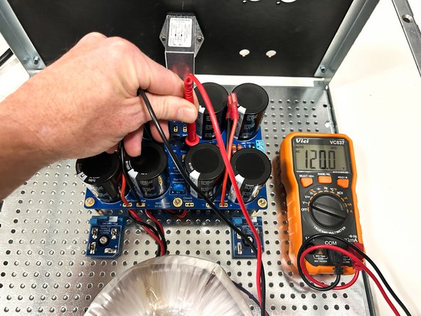
Once full mains voltage is reached, check it at the main board where the transformer primaries are connected. If it does not match your expected mains voltage, stop immediately and turn off the mains power.
-
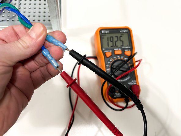
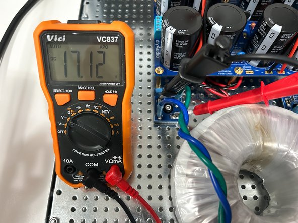
Check the AC voltage across each of the transformer secondaries. It will likely be slightly higher than the voltage noted. As an example for a typical 18VAC transformer, it will measure between 19 and 20VAC unloaded at standard rated mains.
-
Turn off the mains power.
-
Photo 1 - Approximately 120VAC at the transformer primaries. DO NOT hold both probes with one hand. This photo was taken to better demonstrate the location of the probes.
-
Photo 2 - Approximately 19-20VAC at transformer secondary 1
-
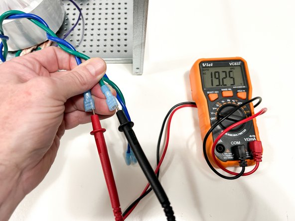
Photo 3 - Identical voltage at transformer secondary 2. Don't worry if they differ by a even a few tenths of a volt. If the voltages differ by 0.5V or more, troubleshooting is necessary.
-
-
-
Triple check to ensure that the secondary windings have been properly identified and separated.
-
The transformer secondaries connect to the rectifiers at the tabs marked AC. It makes no difference which end of the primary winding is attached to which tab.
-
Connect both transformer secondaries to both rectifiers. (4-wires / two rectifiers).
-
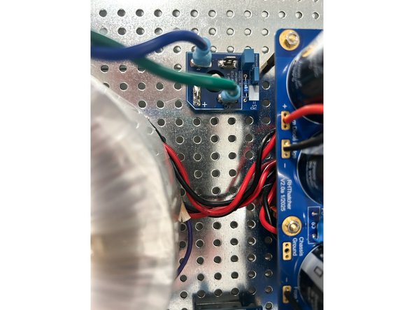
Photo 1 - Properly connected transformer secondary.
-
-
-
Many builders are unsure of results when they measure the voltage at the rectifiers using a basic hand-held DMM. Because the voltage at the rectifiers has not been 'smoothed' or 'filtered', it is not 'Perfect DC'. There is a significant amount of AC ripple.
-
Turn on the mains power.
-
With the DMM set to measure DCV, measure the voltage across the (+) and (-) tabs of both rectifiers. The results will vary widely by the DMM used, but anything above 10VDC would be acceptable at this point. It does not matter if the voltages at both rectifiers are even close.
-
(optional) - With the DMM set to measure ACV, measure the voltage across the (+) and (-) tabs of both rectifiers. Notice how there may still be a fairly high AC component displayed. This measurement is only for amusement / learning. The AC and DC voltages will not sum to the final DC output voltage of the PSU.
-
Turn off the mains power
-
Photo 1 - DC Voltage at one rectifier.
-
Photo 2 - AC Voltage at the same rectifier.
-
-
-
The rectifier PCBs are clearly marked with a (+) and a (-). In addition, for every rectifier of this style, the (+) terminal will be the terminal oriented 90 degrees off of the other three.
-
Connect the main PCB to the rectifiers.
-
It is critical to ensure the proper connections to the rectifiers. Triple check your work to ensure the (+) and (-) pads from the main PCB attach to the corresponding (+) and (-) terminals on the rectifiers.
-
Photo 1 - Rectifier connected properly to the main PCB.
-
Photo 2 - The fully-assembled unit may look something like this.
-
-
-
When checking the DC voltages, ensure that you keep track of the polarities. It may be wise to permanently fix the black / common probe of your DMM to GND and move only the red probe for measurements.
-
There will be 4 measurements. Measure between the (+) and GND and the (-) and GND pads for each side. For this example, final voltages could be anywhere from 24VDC to 27VDC based on mains voltage fluctuations and the transformer chosen.
-
Turn on mains power.
-
Measure all 4 voltages: +VDC Right, -VDC Right, +VDC Left, and -VDC Right.
-
Validate that both channels (left and right) match within 0V1 and that the equal and opposite supplies match within 0V1. If not, troubleshooting may be required.
-
Turn off the mains power.
-
Photo 2 - (+)25V99 is perfectly acceptable. Right side demonstrated.
-
Photo 3 - (-)26V02 is perfectly acceptable. Right side demonstrated.
-
-
-
Reminder - The thermistors used for inrush current limiting will get VERY hot in normal use. DO NOT TOUCH them until it is verified that they have cooled to ambient temperature!
-
When the power supply is used as a part of an "amplifier", the NTC thermistors used for inrush current limiting need time to cool between power cycles. A good rule of thumb is one minute should be allowed between turning the unit off and on again.
-
Quickly turning off and turning on the power (also known as a hot restart) to the amplifier should be avoided.
-
If an accidental hot restart occurs or if power is quickly removed and restored for any reason before the thermistors have sufficiently cooled, the inrush current will be higher than expected, and a fuse could blow. If this occurs, simply replace the fuse. DO NOT increase the amperage rating for the fuse.
-
-
-
Do a little happy dance!
-


Congratulations on building and testing your PSU!
A few things before you run off and start another project:
- This is a build guide by DIYers for DIYers. If you have any suggestions for improvement, notice any errors, or think something could be clarified, please post in the forums. Someone will be looking.
- Please post some pictures of your build in the forum. Nothing makes us happier than seeing completed builds and the creativity of DIYers around the world.
- Make sure to go to the forums and thank Randy for an amazing project.
- Last but not least, please click the button below if you completed the project. It really helps the data dorks.