
Introduction
This is a group of photos overviewing the basic steps necessary to build a DIY Firstwatt / Nelson Pass F5 Class-A amplifier. This build utilizes the v3 circuit board and the kit of circuit board parts available from diyAudioStore.com
-
-
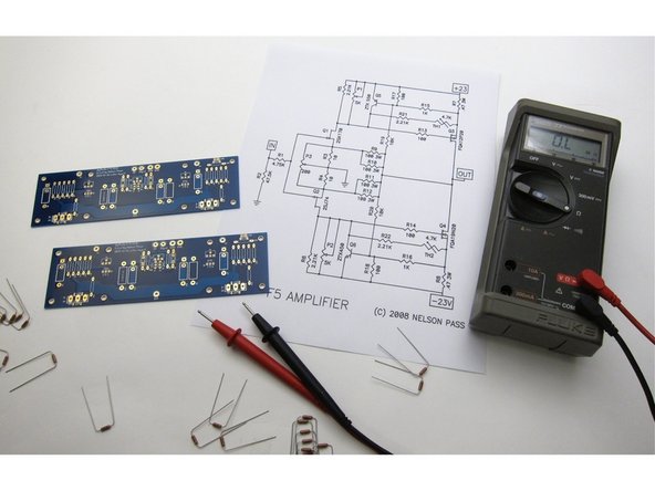
Print this out and have in front of you at all times.
-
Image 1) This is the schematic for the amplifier section.
-
Image 2) Schematic for the PSU section.
-
-
-
Photo 1) The current F5 PCB from the diyAudio store. It has the inclusion of potentiometer P3, and is the third revision of this board, hence "F5v3"
-
Photo 2) Right - PCB bag. Left - Kit of F5 parts.
-
Photo 3) The parts kit includes everting for the amp PCBs except the input Jfets and the LED
-
-
-
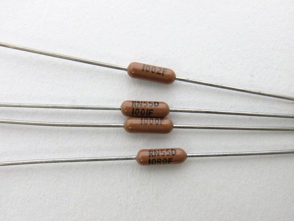
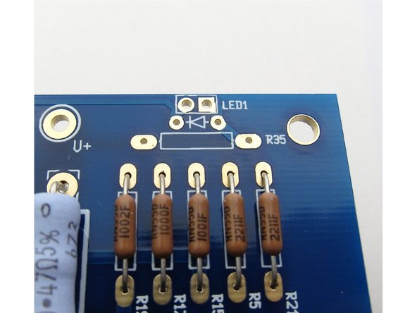
The Dale resistors have thier value printed on the side, the code is 3-digit + multiplier at values greater than 100ohm, and below 100ohm the "R" is the decimal. So, from top to bottom you see 10K (100+2 zeros, 10000ohm) 1K (100+1 zero, 1000ohm) 100 ohm (100+0 zeros, 100ohm) 10.0 ohm (10R0, 10.0 ohm)
-
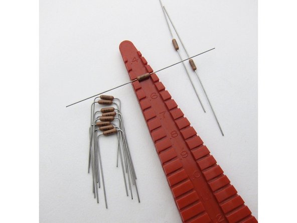
Lead spacing for all small resistors is .5inch (12.7mm)
-
Measure all resistors before inserting into the board. This greatly reduces errors.
-
-
-
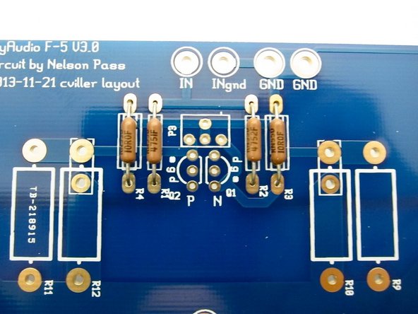
Take the time to bend all the leads so the value is visible, and align them all the same way for easy reading.
-
Photo 1) left side
-
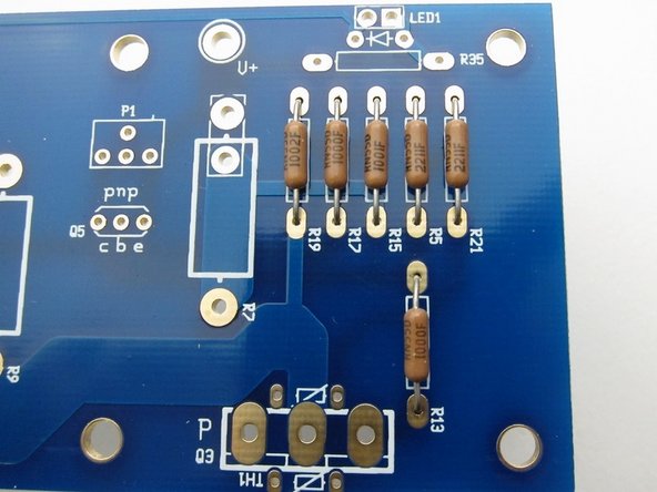
Photo 2) center
-
Photo 3) right side
-
-
-
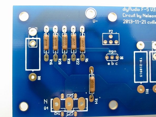
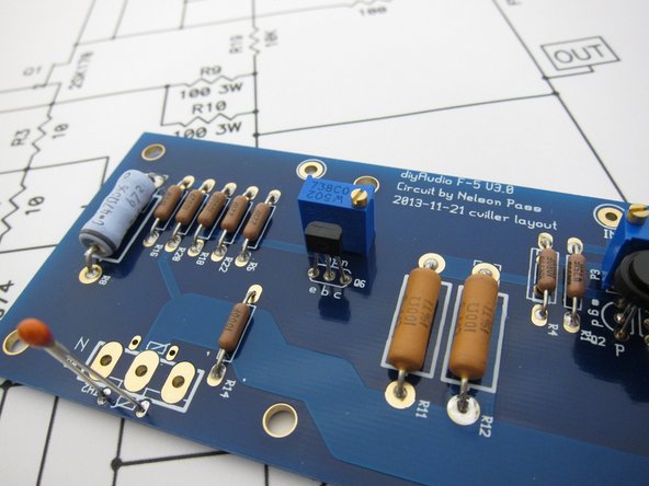
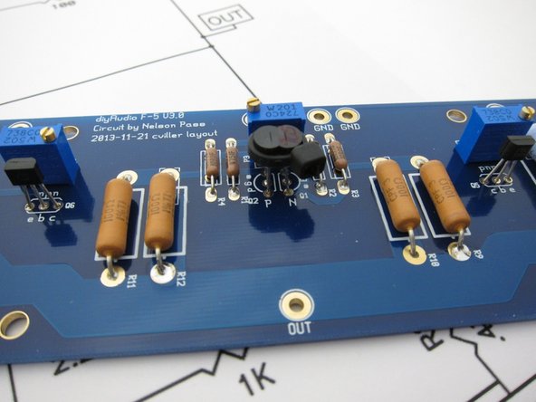
Big resistors installed. Blue are 0.47ohm 3W, Orange are 100ohm 3W. Values printed clearly on the side of each resistor.
-
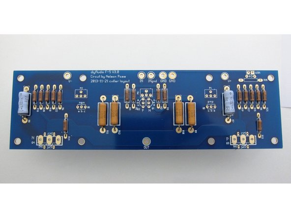
Photo 2) PCB with just small resistors.
-
-
-
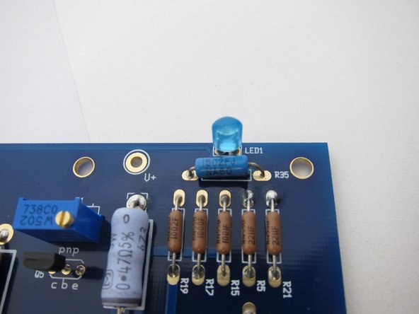
Note that the parts kit does not include the LED or it's resistor, this is so you can choose that you prefer.
-
I used blue and a 15K resistor
-
-
-
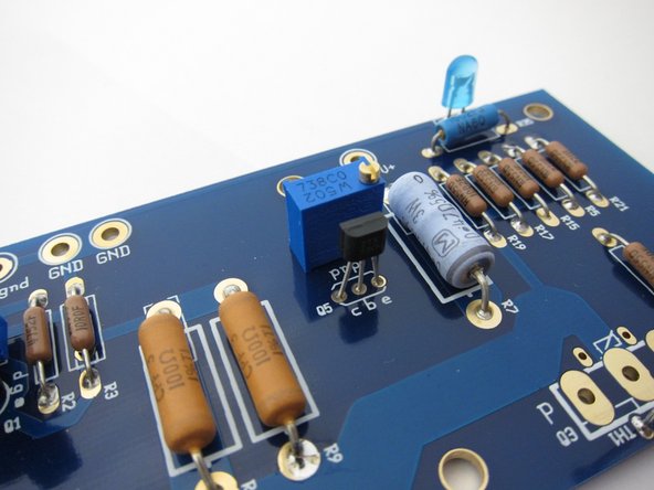
Install the 5K pot and the ZTX450 on this side (Q6). Note the orientation of the transistor. The potentiometer value is almost the same code as the resistors - 502 is 50+2 zeros , 5000 ohms
-
Q5 is the ZTX550, note orientation, and use another 5K pot here.
-
The 200ohm pot mounts in the center, and the Jfets install as shown. The K170 is the N-channel, the J74 is the P-channel.
If you solder P1 and P2 in the orientation shown DO NOT follow instructions from previous build guides that tell you to turn the pots counter clockwise before power up. In the pictured orientation on the V3 board CLOCKWISE sets the pot to 0 bias! I learned the hard way.
-
-
-
Mount the thermistors as shown and don't bend then yet.
-
-
-
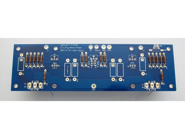
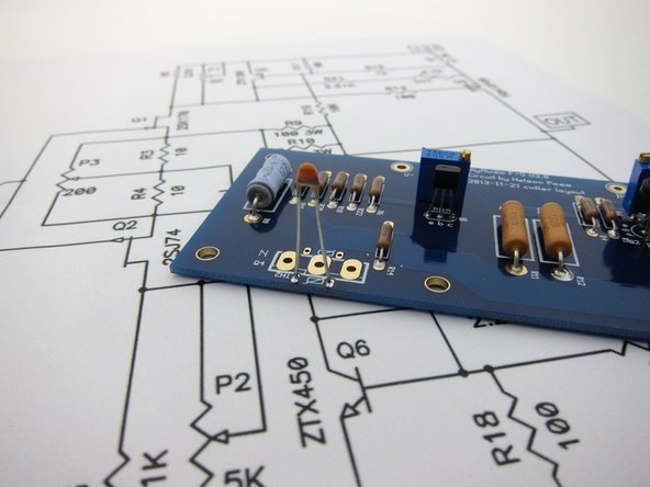
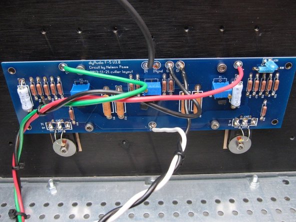
At this point the amplifier PCBs should look like this - all components stuffed except power transistors, and the thermistors not bent.
-
-
-
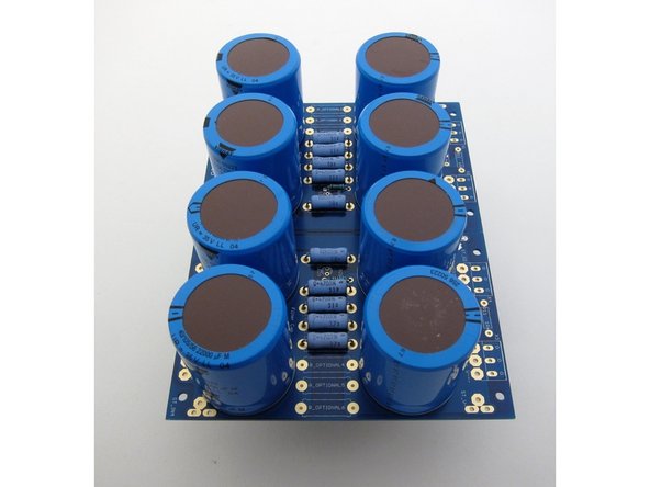
This is the PSU board from the store, the diode section is snapped off and chassis mount diode bridges will be used to save space.
-
Photo 1) input side
-
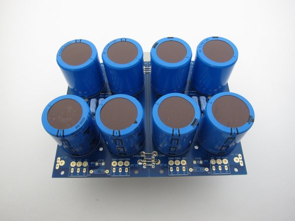
Photo 2) center
-
Photo 3) output side
-
-
-
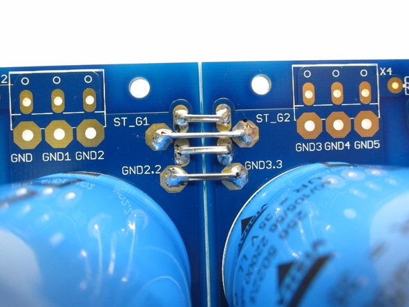
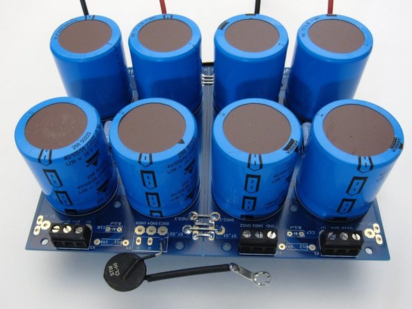
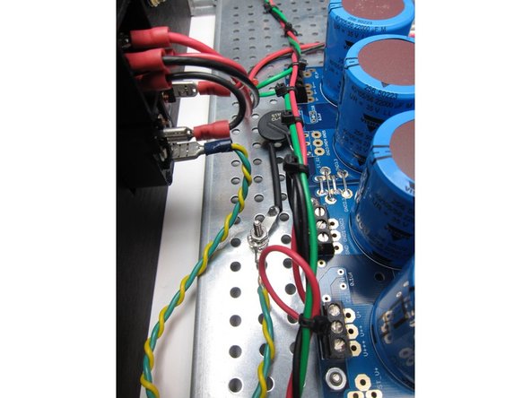
Photo 1) Please connect the two sides of the ground as shown - it won't work properly without it. Use a few wires or lead cut-offs, to insure a solid, quiet, and low-impedance ground.
-
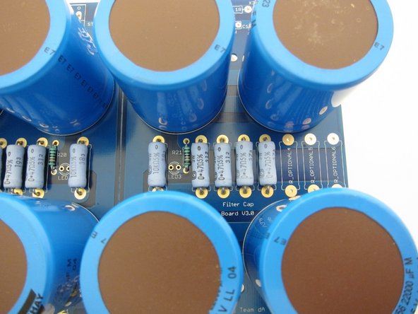
Photo 2) Filter resistors, bleeder resistor, LED resistor. LED not stuffed, choose whichever color you like, you could color code V+ and V-, or make them bright blue to fill the vent holes with color, it's up to you.
-
You can stuff both connector blocks on ground, but if you use one, you will have all the grounds closer to the same place, acting somewhat as a 'star ground'.
-
The CL-60 is acting as a ground loop breaker, elevating the amplifier circuit with a resistance above mains earth, but can flow current if there's a fault.
-
-
-
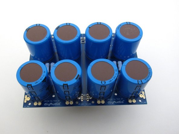
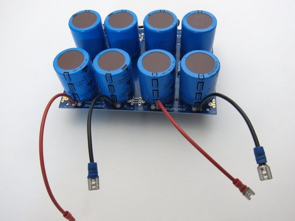
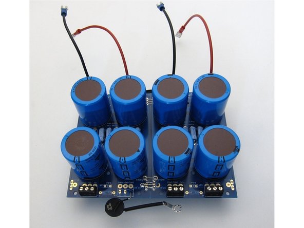
PSU ready for installation. Blocks installed, wires to connect to diodes ready, thermistor with star washer.
-
-
-
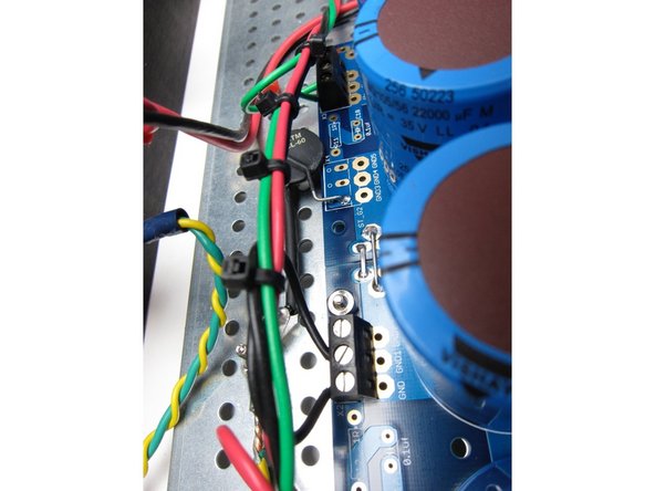
Diode bridges to PSU board.
-
-
-
Safety earth (Green Yellow) is connected from the power switch module to the chassis. Use a star washer to ensure a solid connection.
-
-
-
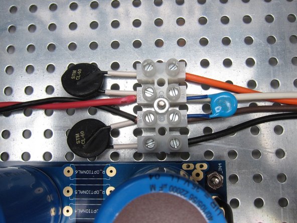
Terminal block. 120VAC wiring shown. AC from switch in from left (Red Black) CL-60's, the blue disc is the X1/Y1 rated capacitor, and transformer primaries are out the right.
-
-
-
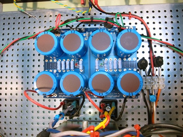
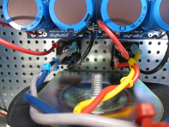
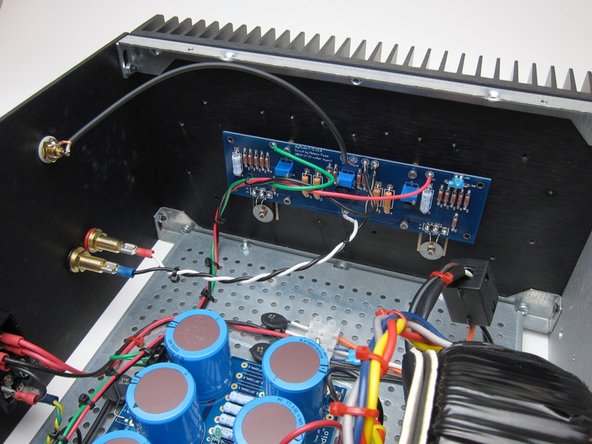
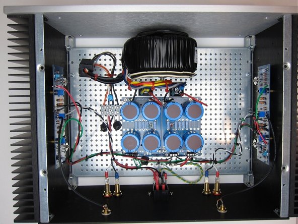
Connections from amp PCB to back panel.
-
Try to arrange the wires so they are not in the way of the potentiometers. Zip-ties are your friend!
-
Note the small thermistors are bent down now and touch the washers holding the Mosfets.
-
-
-
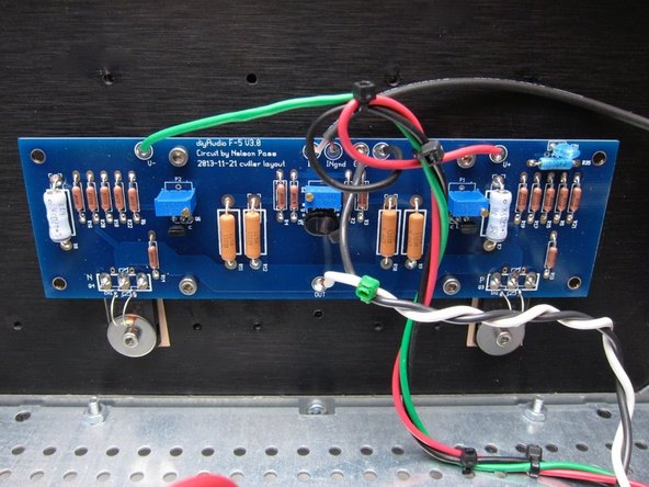
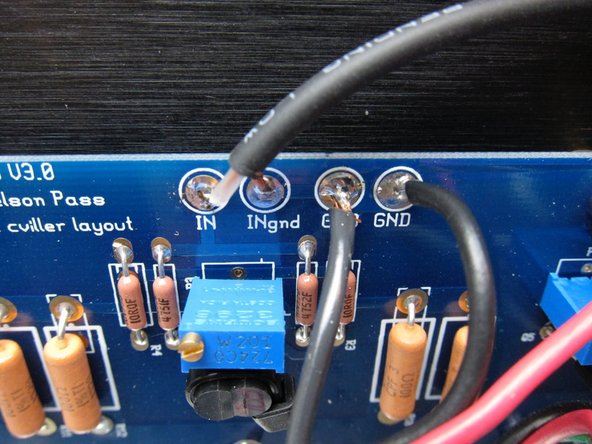
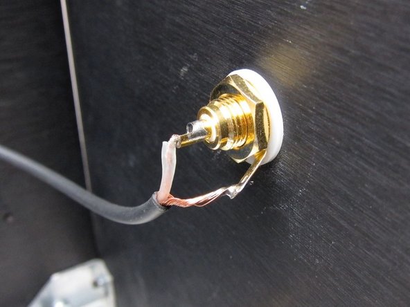
The PCB connections to GND are all tied together, but it's still nice to have individual holes for the wires. Input ground from the RCA jack, speaker, PSU.
-
Photo 2) RCA wiring
-
-
-
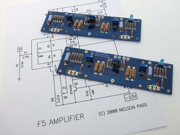
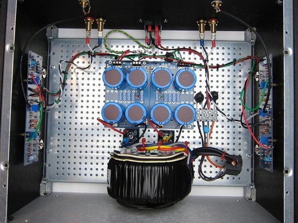
Photo of completed amp.
-


Cancel: I did not complete this guide.
32 other people completed this guide.