
Introduction
What Are We Building?
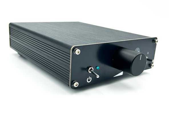
This guide covers the assembly of Gray Matter's B1 Special Operations (B1SO) Pre-Amplifier.
What Is Covered In The Guide?
This guide will cover every step from start to finish along with helpful pictures.
Who Can Build It?
The project is considered suitable for novice DIYers. Builders should be proficient in through-hole PCB soldering. There is a relatively high parts count, and the parts are relatively closely spaced, but someone that is proficient in through-hole soldering and that can follow step-by-step instructions should be able to complete the project successfully.
What Else Is Needed?
Everything you need to build your project (except tools) is included in your kit. We've even included a helpful list of tools.
-
-
A black bullet is explanatory or contains valuable information.
-
Everything in this guide is important, but here's how you'll know something is REALLY important.
-
A green bullet is the mark to do something.
-
A yellow bullet indicates a fun fact.
-
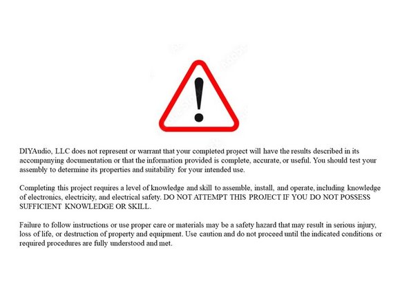
Warnings will be noted with a warning symbol and bold, red, underlined text. Pay Attention!
-
Tips and tricks and helpful reminders will be noted with an information bullet.
-
Photo / Image captions and information will be noted with the Photo/Image Icon.
-
-
-
Click on the image to enlarge and read the warnings carefully.
-
-
-
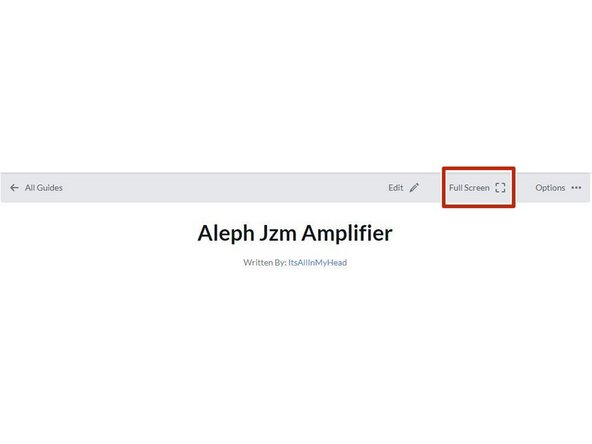
Your first "real" black bullet. You may notice that you have the option to view in "Full Screen". I like it either way, but I prefer full screen. This web platform works well with tablets too. I've tested it with various monitors of various aspect ratios and tablets. Choose what looks best to you. The printed .pdf format is nice too.
-
Image 1 - To switch to "Full screen", take note of the box around "Full screen" at the top of the guide above the header / title. That's where you click to move to Full Screen.
-
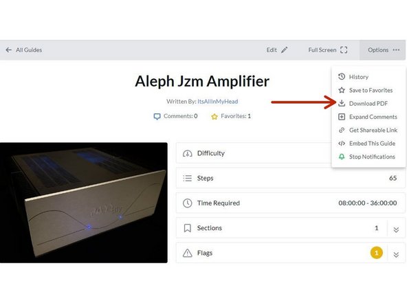
Image 2 - Note that you can download this guide as a .pdf and print it. Click the options button in the upper right.
-
In all the on-line views, if there are multiple images and/or photos within a step, mouse-over or tap/click as appropriate to make which ever one you'd like the primary image (the biggest one).
-
Mousing over / tapping on the primary image will change the cursor to a magnifying glass. Clicking / double tapping will open a new tab or enlarge and center the image on your screen.
-
In full-screen mode, the keyboard right and left arrows or clicking the arrows in the upper right will advance or reverse one step.
-
Your first "real" green bullet. Choose if you want to view in full screen or standard (if you haven't already) and/or print a copy of the guide.
-
Get started. Move on to step 4.
-
-
-
All mistakes are preventable, and this guide moves slowly through each step.
-
The most common issues with builds are mis-stuffed parts and poor solder joints.
-
Symptoms from mis-stuffed parts typically manifest quickly. The impact from an improper part placement can be benign, or you could release the "magic smoke".
-
The impact of poor soldering varies. A short/bridge can be catastrophic, but they are usually easy to see and correct. With partial coverage or a cold joint, symptoms may not manifest until you least expect them, and they may be intermittent. Inspect every joint under magnification. You'll be glad you did.
-
DMM issues can lead to frustration.
-
Check the batteries. When in doubt, replace the batteries.
-
Make sure your probes are reading "0 Ohms" resistance probe to probe or are appropriately compensated.
-
Make sure your probes are connected properly. It is best practice when taking a DC voltage measurement that the black (common) probe is to ground as appropriate. For any troubleshooting, it is likely that noting the proper polarity will matter.
-
-
-
The notation of voltages requiring a decimal place will have a "V" in place of the decimal. 24V5 is 24.5 Volts or 24,5 Volts.
-
The notation of resistance requiring a decimal place will have a "R" in place of the decimal. 0R5 is 0.5 Ohms or 0,5 Ohms.
-
The notation of Amperage requiring a decimal place will have an "A" in place of the decimal. 1A1 is 1.1 or 1,1 Amperes.
-
-
-
The most common action you'll take throughout the guide is to "install" your parts AKA stuff the PCB. Parts installation includes:
-
Ensuring you have the correct parts to match the PCB silkscreen / schematic.
-
Ensuring the leads are clean / free from finger oils, and are bent to the proper pitch (if applicable).
-
Validating the orientation of the part (as applicable) and inserting the part into the boards along with ensuring any vertical spacing (as applicable).
-
Soldering the parts into place.
-
Cutting the leads to the proper length*
-
It is also acceptable to clip the leads to the correct length prior to soldering. There are compelling reasons to do it either way. If you are unsure, watch a few videos, read a few articles, and do some test soldering of your own to see what works best for you. If you choose to clip prior to soldering, use the correct tool.
-
Cleaning and inspecting the joint. It is strongly recommended to use magnification and good lighting to inspect every joint.
-
-
-
This guide does not cover how to solder / install through hole parts. There are a variety of great ways to install a part and achieve a proper solder joint, but there are common themes throughout. Below are a few links. See what works best for you. Neither diyAudio nor the author have any affiliation with any of the companies or persons linked.
-
-
-
-
-
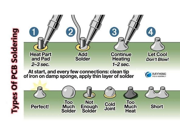
Image 1 - A basic soldering sequence and examples of both good and poor joints. Taken from the Rayming PCB & Assembly Guide linked above.
-
The key variables to soldering are the type of solder chosen, the tip used, and the tip temperature. These all vary widely between users and are inter-related. If you are new to electronics, the best solution is practice. Scrap electronics and inexpensive parts are a wonderful way to learn.
-
Leaving the iron tip on the joint for longer than around 5 seconds is not a substitute for too small an iron tip or too low a temperature. If you need to reflow a joint, or if the solder isn't flowing, flux is your friend.
-
-
-
Plan your build. Read this guide a few times before you even take the first part out of the bag.
-
Go slowly. You're not getting paid to do 100 boards a day. This should be relaxing and fun. A lot of errors can be traced back to lack of attention and rushing.
-
The ONLY parts within reach should be for the step you are working on at the moment. Many parts look very similar.
-
Move the boards and your body around to give yourself the best angle to solder each part. Get close to your work and use magnification. A well-lit workspace is important. You don't stand a chance if you can't see!
-
Before moving to the next part, triple check your work. Hopefully you won't make any errors, but it is much easier to remove one part than many to fix an error. Using the included documents and following a basic sequence will assist with error-free construction.
-
Take plenty of breaks and stop at any point confusion or frustration sets in. Stop any time you mentally or physically need to recharge.
-
Try to keep distractions to a minimum. Silence the mobile phone, and keep it out of arm's reach.
-
Neatness counts!!! Take pride in your work. You'll be happy you did.
-
-
-
Print a copy of each of the relevant documents.
-
If you are in standard view mode, scroll to the end of the guide.
-
If you are in full-screen mode, go back to the introduction and click on the documents tab.
-
Tidy up your workspace. Keep in mind that you'll be working with a very hot soldering iron, and it can be easy to misplace parts. A few recomemndations:
-
No other parts for any other projects should be within arm's reach.
-
The floor and the area around the workspace should be clean, just in case a part escapes.
-
-
-
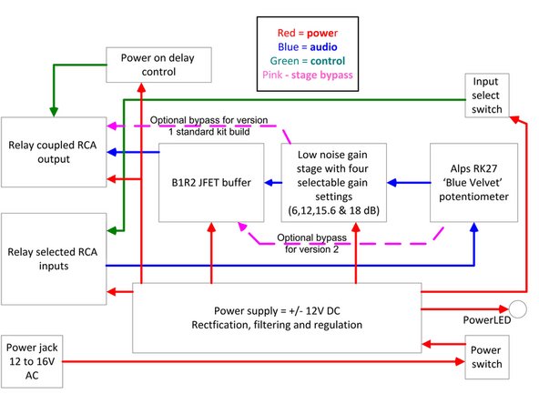
The B1SO can be built in three configurations
-
Version 1 - Amplifier with gain. The JFET buffer is omitted and bypassed. This is the version fully demonstrated in this guide. The parts included with kits from diyAudiostore.com are for Version 1.
-
Version 2 - JFET buffer only. The gain stage is omitted and bypassed. See the Addendum in the documents section for instructions
-
Version 3 - Both the amplifier with gain and the JFET buffer. See the Addendum in the documents section for instructions
-
Choose which version you will build and ensure you have the appropriate steps noted.
-
-
-
Image 1 - This is a block diagram of the overall circuit.
-
-
-
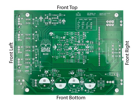
Throughout the guide, the top, bottom, left, right, front, back, or combinations will be referenced. Here is a quick overview.
-
Look over your boards and get familiar with the parts placement.
-
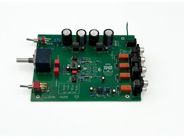
Photo 1 - Front view of the PCB.
-
Photo 2 - Not all parts will be stuffed. This guide demonstrates the build of "version 1". Amplifier with gain. The JFET buffer is omitted and bypassed. The AT pads can be used for terminal blocks if you choose to mount the board in a different chassis.
-
The PCB will not be exactly as shown. A very slight revision was made moving the mounting point of the potentiometer. This will not affect your build.
-
-
-
There are 9 bags of parts with included with your B1SO kit. It's recommended to only open the bags as you need them. Keep all the other bags together and in a location where they won't get mixed with other projects or lost.
-
As you open a bag, place all the parts carefully in a bowl or somewhere they will not get lost, knocked onto the floor, accidentally spread around your workbench, or mixed in with other parts not associated with this project.
-
Find the bag with the small ceramic caps.
-
Many people like to separate their parts by type. For this project, it's not necessary, but choose whatever method works best for you. It's fairly simple to keep all the parts together and select only what is required for a particular step.
-
-
-
The 0.1uF Ceramic Caps are the small gold caps.
-
Install C11, C12, and C91
-
Photo 1 - Caps Installed
-
-
-
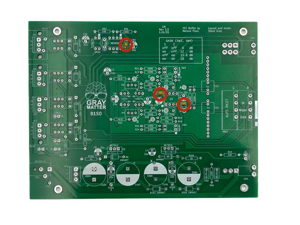
Do not install R19, R20, R25, or R26
-
Remember to measure the resistance for every part before installation and follow the validation / installation / inspection process.
-
It is helpful to use a lead forming tool. The pitch for all small resistors is 0.5 inches (about 13mm). The pitch for the large resistors is 0.6 inches (about 15mm).
-
Having all the resistors oriented the same way helps tremendously with troubleshooting. In this build, the bands will read from left to right or bottom to top. The kit includes all 1% tolerance resistors, so the large brown band is read last.
-
Raising the large 3W resistors, R103 and R104, off of the PCB helps with airflow and keeps things cooler. Use a coin or something handy to keep them raised slightly above the board when soldering. Remember to remove the coin or other tool.
-
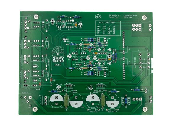
Install all the resistors.
-
Photo 1 - When all of the resistors are installed, your board should look like this.
-
-
-
Ensure that you orient the diodes properly!
-
Diode polarity is indicated by the gray band at one end. Ensure that you match the band on the diode to the white band on the PCB silkscreen.
-
Install D5, D6, D91, D92, D93, D94, D101, and D102
-
Photo 1 - PCB with Diodes Installed
-
-
-
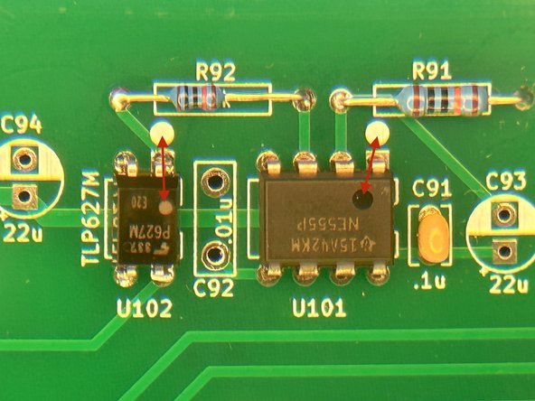
The orientation of U101 and U102 is critical! They are also more challenging to remove and correct if they are installed incorrectly. Please triple check the orientation before soldering.
-
Photo 1 - The dot on the parts indicates pin 1 and should be next to the dot on the silkscreen and the square pad. Do no use the orientation of the lettering to determine the orientation of the part.
-
Install U101 and U102
-
-
-
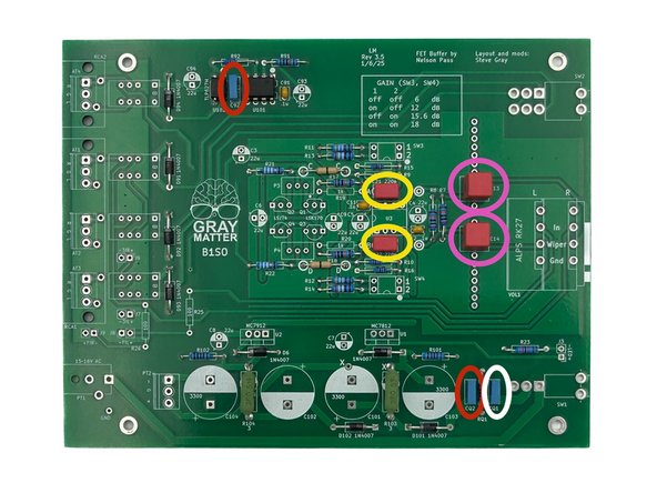
The kit contains 4 different values of film capacitors. They should be easy to separate and install properly. Ensure they are installed in the correct places.
-
Install CQ1. Make sure that it is the single 0.15uF capacitor. It looks a lot like CQ2 and C92. Marked in white - photo 1
-
Install CQ2 and C92. Marked in red - photo 1
-
Install C21 and C22. Marked in yellow - photo 1
-
Install C13 and C14. Marked in pink - photo 1
-
Photo 1 - All film caps installed
-
-
-
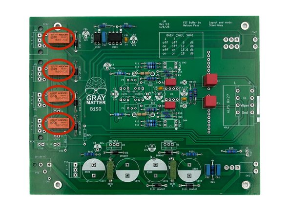
The relays are keyed, so they can only be installed one way. Use a piece of tape if necessary to hold them in place while soldering.
-
Install K1, K2, K3, and K201.
-
Photo 1 - Relays Installed
-
-
-
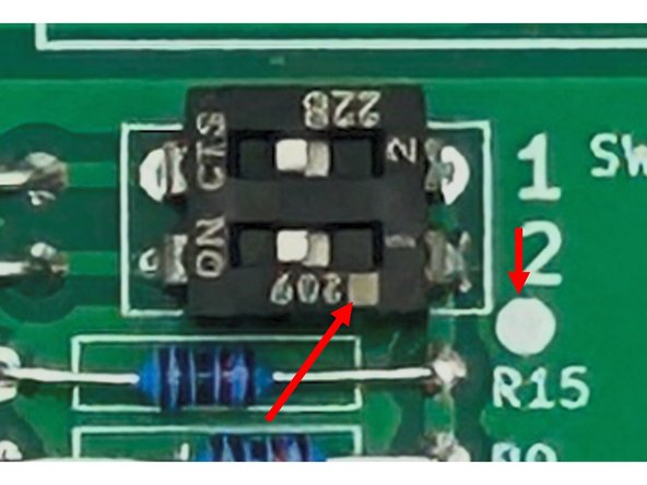
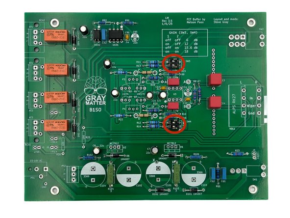
Please be sure to read the instructions carefully to ensure proper orientation of the DIP switches.
-
The DIP switches have a dot to note the orientation / pin one. Ensure that the dot on the switch aligns with the dot on the PCB silkscreen.
-
Photo 1 - Ensure you match up the dots for both switches. Do not use the number on the switches and silkscreen as a guide. The switch numbers on the board are reversed from the legend on the switches themselves.
-
Install SW3 and SW4
-
Photo 2 - DIP Switches Installed
-
-
-
The photo in this step does not perfectly align with the parts shown installed. It is a little easier to install the small electrolytics, now particularly for clearance around U3. At this point, the socket for U3 should be installed, but U3 should not be installed.
-
Do Not Install C6 or C9
-
Be careful to observe proper polarity for electrolytic capacitors. The side with the wide stripe is the side with the ‘-‘ lead. The ‘-‘ lead itself is also indicated by its shorter length.
-
Install C3, C4, C5, C7, C8, C93, and C94.
-
Photo 1 - All Small Electrolytics Installed. Note 'X' on C6 and C9 - Do Not Install.
-
-
-
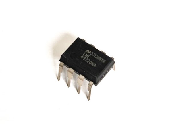
Kits may be provided with the OpAmp (U3) in the SOIC package or in the DIP-8 package. They perform identically. The parts are sourced based upon availability.
-
If your kit has the DIP-8 version, it will look like Photo 1. Skip to Step 24
-
If your kit has the SOIC version, you will have the components in Photo 2. Move on to Step 23.
-
Photo 1 - DIP8 OpAmp
-
Photo 2 - SOIC OpAmp
-
-
-
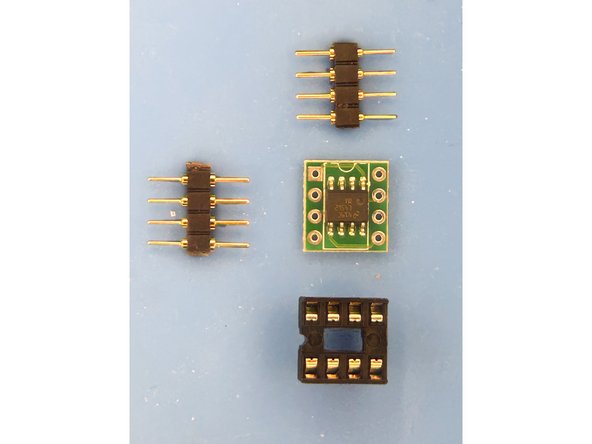
Gather U3 (installed on the small PCB), the two sets of pin headers, and the DIP socket.
-
Photo 1 - U3 on PCB. Pin headers, DIP socket
-
Install the pin headers into the DIP socket and place the PCB over the pins to keep them spaced properly. I prefer the flat side of the pins to sit against the PCB.
-
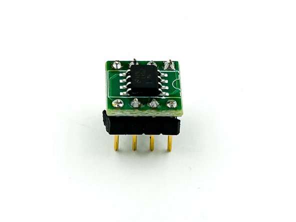
Solder the PCB to the pin headers at all 8 points. Remove the U3 assembly from the DIP socket.
-
Photo 2 - U3 PCB Installed on Pin Headers.
-
-
-
The op-amps chosen for this circuit are excellent. If you choose to roll op-amps, do so at your own risk. For those that have DIP-8 op-amps, and know they will not roll op-amps, you may choose to solder the op-amp directly to the PCB.
-
Solder the DIP-8 socket for U3 to the main PCB or solder U3 directly to the PCB. Align the groove in the socket with the 'groove' noted on the PCB silkscreen.
-
Do Not Install U3 into the socket yet. The DIP-8 OpAmps can be a challenge to remove and re-insert without bending the pins. You'll install it after basic voltage checks.
-
-
-
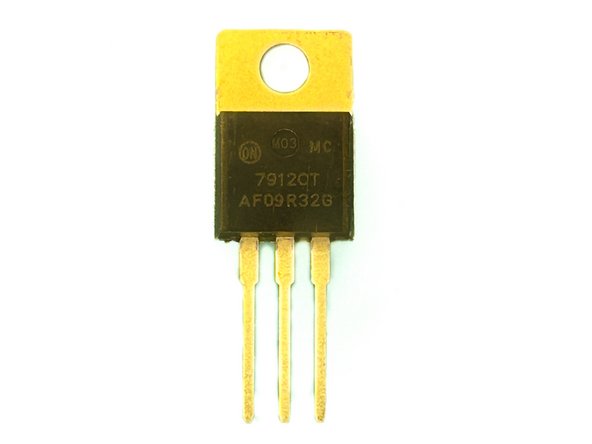
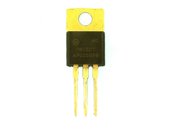
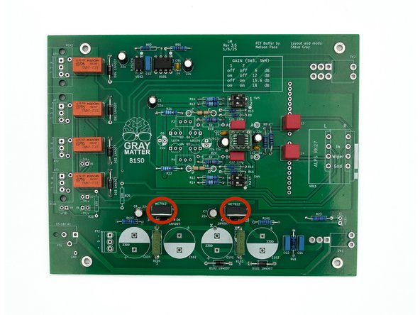
Check the markings on the regulators to be sure the 7912 and 7812 are inserted in their correct locations. The locations are clearly marked on the PCB silkscreen.
-
Photo 1 - MC7912
-
Photo 2 - MC7812
-
The metal side of the regulator aligns with the three rectangles on the silkscreen. The metal side of the regulators will face the big caps.
-
Install U1 and U2.
-
Photo 3 - Regulators Installed
-
-
-
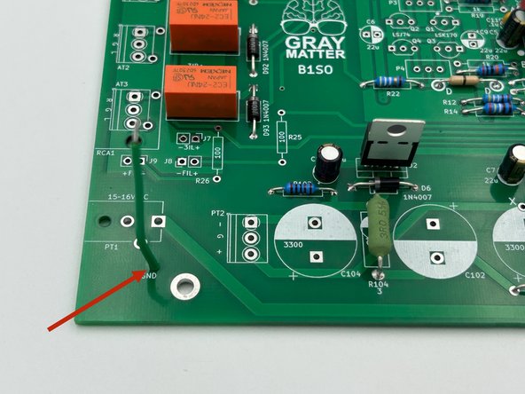
Strip approximately 1/8" (3mm) from each end of the green multistrand wire and tin both ends.
-
Solder the wire to the pad marked GND in the bottom left of the PCB.
-
Photo 1 - GND wire installed.
-
-
-
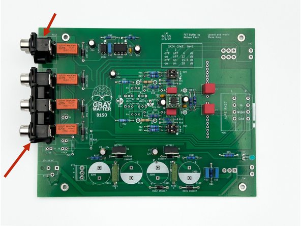
The connectors should snap in. Be sure they are flush against the PCB before soldering.
-
Install RCA1 and RCA2
-
Photo 1 - RCA Connectors Installed
-
-
-
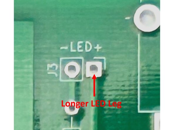
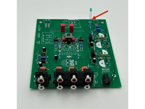
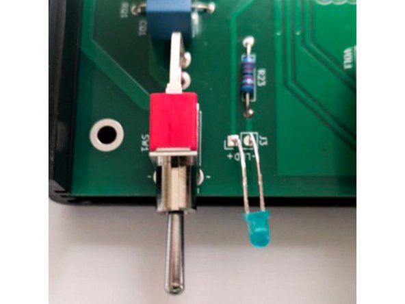
It is important to install the LED in the correct orientation and at the correct length. Please review carefully.
-
Photo 1 - The longer lead is the positive lead. The longer lead is inserted into the square pad marked with a (+).
-
Slide the LED into the holes until the distance between the PCB and the bottom of the LED is about 1" (25mm). Solder the LED into place and trim the leads.
-
The LED leads will be bent later to fit the front panel.
-
Photo 2 - LED Installed.
-
-
-
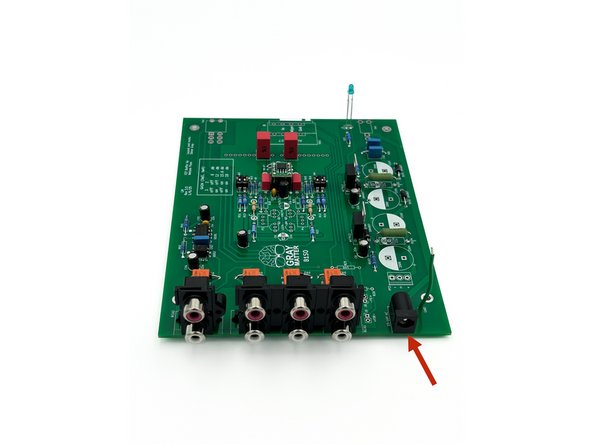
Ensure the 2.1 x 5.5 barrel connection is sitting flush with the PCB prior to soldering.
-
Install PT1
-
Photo 1 - DC Power Jack Installed
-
-
-
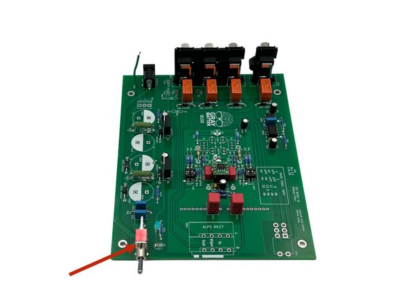
Ensure the switch is sitting flush with the PCB and square to the edge of the board. The holes for the switches are slightly larger than needed. Be sure they are held properly in place when soldering
-
Install SW1
-
Photo 1 - Power Switch Installed
-
-
-
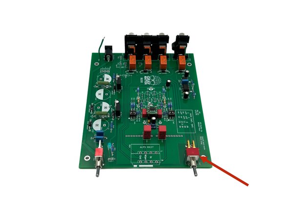
Ensure the switch is sitting flush with the PCB and square to the edge of the board. The holes for the switches are slightly larger than needed. Be sure they are held properly in place when soldering
-
Install SW2
-
Photo 1 - Input selection switch installed
-
-
-
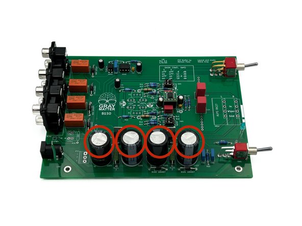
Be careful to observe proper polarity for electrolytic capacitors. The side with the wide stripe is the side with the ‘-‘ lead. The ‘-‘ lead itself is also indicated by its shorter length.
-
Install C101, C102, C103, and C104.
-
Photo 1 - Large Caps Installed.
-
-
-
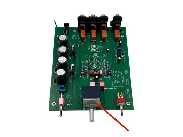
Ensure the pot is sitting flush with the PCB and is aligned squarely with the edge of the PCB before soldering.
-
A piece of tape and/or holding the pot in place while soldering a single pin to ensure alignment before soldering the remainder of the pins is helpful. If alignment is off, simply reheat the single joint and re-align.
-
Install the Alps Blue Velvet potentiometer in VOL1
-
Photo 1 - Volume Control Installed
-
-
-
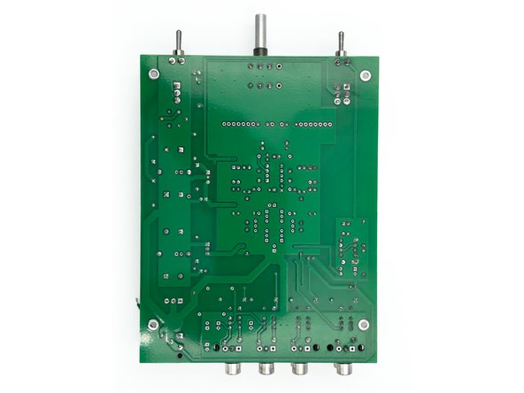
Cleaning the PCB is not strictly necessary unless you are using a solder with a flux or resin specifically noting that it requires cleaning. However, it is strongly advised to clean your PCB if you have not been doing it consistently after soldering each joint. It makes final inspection much easier. Plus, it looks nice.
-
A highly concentrated Isopropyl alcohol is known to work well and has been tested on these PCBs. However, the choice of solvent varies based upon the solder you use.
-
Other chemical flux removers can be more effective with various solders. Consult the spec sheet for your particular solder. If you choose to use a commercial flux remover, check a small portion of the board to ensure it will not lift the solder mask.
-
Clean the back / solder side of the PCB using your preferred method. You should not need to clean the top of the board. Do not "flood" the board. Do not put it under running water. Many of the parts including the relays, switches, and the pot are not sealed. Be careful that you don't get liquid inside any of the parts.
-
Photo 1 - A nice, clean PCB.
-
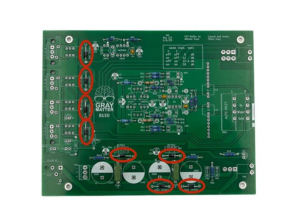
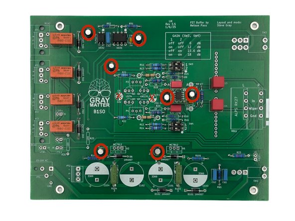
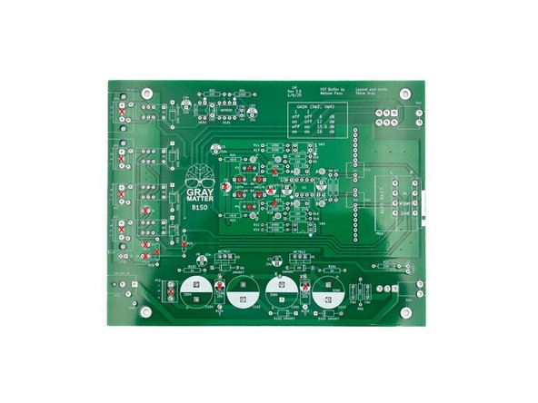
Go over the board back and front and inspect the parts and joints. Use magnification and good lighting. Pay particular attention to diode orientation, proper insertion of the regulators, and the orientation of all electrolytic capacitors. Check every area for bridges / shorts.
-
Photo 2 - Make sure none of these parts are installed. If they are, another part in another location is missing (if you're using the parts provided in the kits)
-
Photo 3 - Your board should look like this.
-
-
-
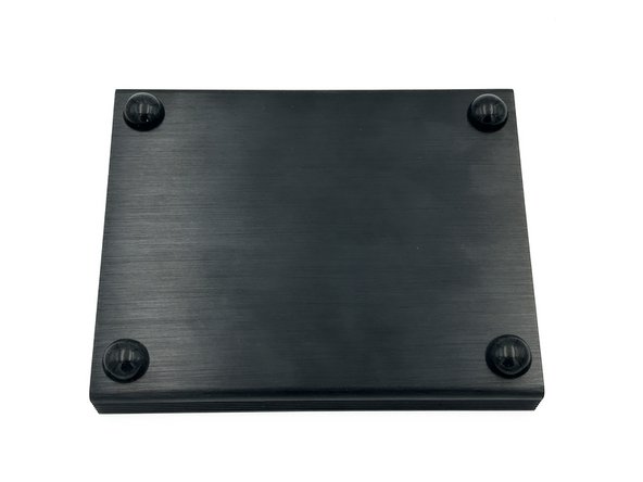
Choose one half of the clamshell chassis and install the 4, stick-on feet at each corner. Placement is not critical, but the feet should not be removed and replaced, so be careful with your alignment. The side with the feet is now the bottom of the chassis.
-
Note - Feet may be a different style and vary in color based on availability.
-
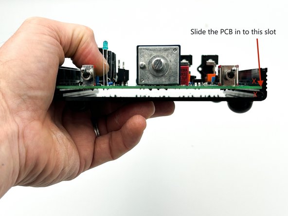
In the bottom chassis half, slide the PCB into the middle slot in the side rails with the components facing toward the top. See photo 2.
-
Photo 1 - Feet installed on the bottom of the chassis.
-
Photo 2 - Slide the PCB into this slot.
-
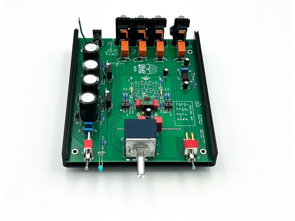
Photo 3 - Top view.
-
-
-
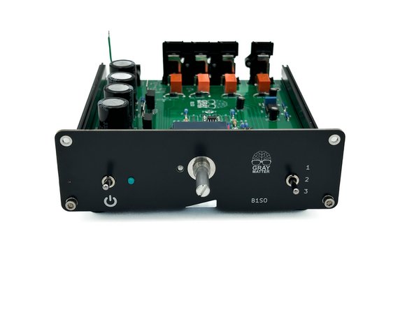
Gently bend the legs of the LED so that the tip of the bulb extends beyond the edge of the chassis. It does not need to be perfect.
-
Ensure that the two legs of the LED do not touch / short together.
-
-
-
Optional - If you'd like, use a black "Sharpie" or similar to color the edges of your front panel. It is a matter of personal taste. If you choose to color the edges, be careful to not get ink on the face of the front panel. If you do, simply wipe it off using isopropyl alcohol.
-
Gently slide the front panel over the power switch shaft, the potentiometer shaft, and the input selector switch shaft.
-
To make installing the front panel a little easier, the selector switch can be set to position 2. The power switch can also be held at its center with your fingers. It has no detent to support maintaining that position.
-
If for any reason, the switches and volume control do not line up properly with the front panel, do not force them. Check that the board is inserted into the correct slot on the chassis and adjust as necessary.
-
Gently insert the LED into the hole in the front panel. A pair of needle-nose pliers is useful. Once again, check to ensure that the LED legs do not touch.
-
Use two hex-head machine screws to secure the panel to the clamshell. Ensure they tight to ensure a good electrical connection is made between the front panel and the chassis side rails, but do not over-tighten.
-
Photo 1 - Front Panel Installed.
-
-
-
Optional - If you'd like, use a black "Sharpie" or similar to color the edges of your front panel. It is a matter of personal taste. If you choose to color the edges, be careful to not get ink on the face of the front panel. If you do, simply wipe it off using isopropyl alcohol.
-
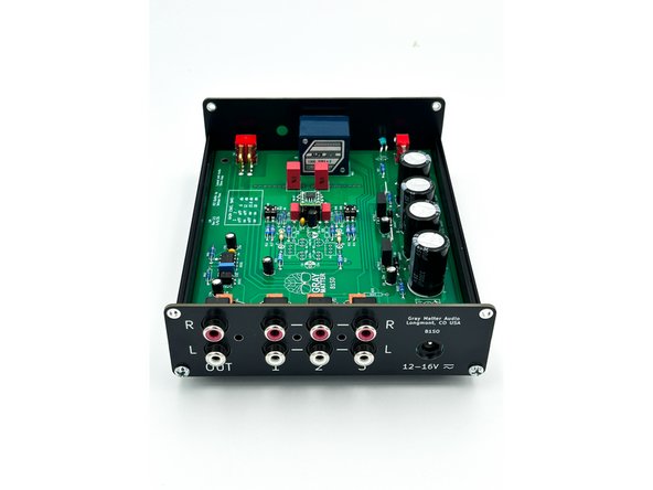
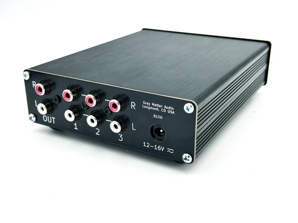
Slide the back panel over the RCA jacks. Ensure the jacks are properly aligned within their holes on the panel.
-
Use two silver, Phillips-head machine screws to attach the panel to the bottom clamshell.
-
Photo 1 - Back panel installed on bottom clamshell
-
-
-
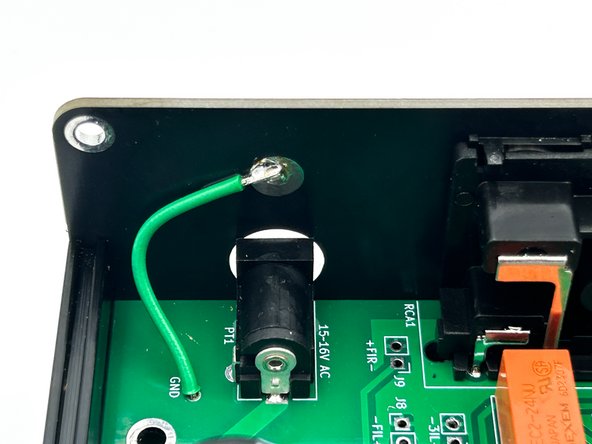
If you haven't already, tin the end of the green GND wire.
-
Solder the green GND wire to the circular pad on back panel, as shown.
-
Photo 1 - GND wire soldered to back panel.
-
-
-
It is much easier to check the power supply and relays before the chassis is completed.
-
Turn off the power switch.
-
Plug the power transformer (a.k.a. the wall-wart) into a mains outlet.
-
Plug the power transformer barrel jack into the power connector on the back panel.
-
Turn the power switch on. The LED should illuminate.
-
-
-
Polarity of the voltage measurements is critical. Make sure that the probes are placed as noted.
-
If you haven't followed instructions, gently remove U3 from the socket
-
Measure the voltage between GND (black DMM probe) and pin 8 (red DMM probe) of the op-amp socket. You should measure +12VDC +/- 10mV
-
Measure the voltage between GND (black DMM probe) and pin 4 (red DMM probe) of the op-amp socket. You should measure -12VDC +/- 10mV
-
Flip the input selection switch to all positions. You should hear the relays click faintly.
-
Turn off the power switch and disconnect the power supply.
-
If both voltages measure correctly, and if the relays are functioning, install U3. Double-check the orientation.
-
If either voltage measurement is incorrect or if the relays do not click, STOP and troubleshoot. If needed, seek assistance in the diyAudio forum in the B1SO Discussion Thread.
-
-
-
Place the top clamshell onto the bottom clamshell. They are keyed and will only install one way.
-
Use the two remaining hex-head machine screws to attach the front panel to the top clamshell.
-
Use the two remaining silver, Phillips-head machine screws to attach the back panel to the top clamshell.
-
Install the the large nut on the potentiometer shaft. Do not over tighten but be sure a good electrical connection is made between the nut and the pad on the front panel. This grounds the knob, which prevents hum when you touch the knob.
-
Install the three, Phillips-head, sheet metal screws to anchor the RCA connectors to the back panel. The screws may be black or silver. Do not over-tighten. (Photo shows black screws).
-
Attach the volume knob to the potentiometer shaft using the included 1mm hex key.
-
Photos 1 and 2 - Looks fantastic!
-
-
-
Ensure the power is off on the power amp you will use.
-
Ensure the B1SO power supply is connected and plugged into the mains socket. Ensure the B1SO power switch is off. Turn the B1SO volume all the way down.
-
Connect the RCA cables from the B1SO output to the power amp’s inputs.
-
Connect your source device(s) to the B1SO input(s).
-
Turn on the B1SO power switch.
-
Turn on the power amp.
-
Use the B1SO source select switch to choose your source. Adjust the volume to your desired level and enjoy.
-
Do a little happy dance!
-


Congratulations on building the B1 Special Ops.
A few things before you run off and start another project:
- This is a build guide by DIYers for DIYers. If you have any suggestions for improvement, notice any errors, or think something could be clarified, please post in the forums. Someone will be looking.
- Please post some pictures of your build in the forum. Nothing makes us happier than seeing completed builds and the creativity of DIYers around the world.
- Make sure to go to the forums and thank Steve for creating an amazing project.
- Last but not least, please click the button below if you completed the project. It really helps the data dorks.
Cancel: I did not complete this guide.
4 other people completed this guide.