
Introduction
In July 2020 we released an updated version of the ACA called the ACA V1.8.
List of all differences between V1.6 and V1.8:
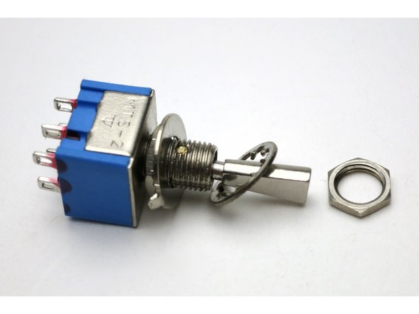
- Rear switch is a 3 position DPDT instead of 2 position, necessitating a change in wiring
- Rear panel is printed with a connection diagram
- Chassis rails are improved using weld nuts and secured by bolts
- Blade terminals are included for the front power switch
- Longer wire
- LED resistors have been changed from 10k to 33.2k to reduce LED brightness
Please note that the PCB did not change whatsoever between 1.6 and 1.8, and so the PCB included in all 1.8 kits says "V1.6". That's the correct version of the PCB.
To build V1.8:
- Print out and use the ACA V1.8 wiring diagram.
- Follow the ACA V1.6 build guide, but follow the V1.8 wiring diagram
- Review the comparison of the V1.6 and V1.8 wiring shown below
The build guide shows how to solder your power switch. Some early kits may include female spade connectors - if your kit has them we don't recommend you use them as they can be so tight as to be problematic. Just follow the instructions for soldering noting not to linger and overheat the switch.
If you have any questions please post them in the ACA Kit 1.6/1.8 Discussion Thread where you will get swift and comprehensive answers.
Cheers!
PS V1.5/V1.6 owners: In October will be offering V1.5/V1.6 to V1.8 make-up kits for builders who have already built a V1.6 (or earlier) and want to bring it up to V1.8 specification (or build matching monos). We'll email you when they are available.
-
-
ACA V1.6 wiring vs ACA V1.8 wiring
-
-
-
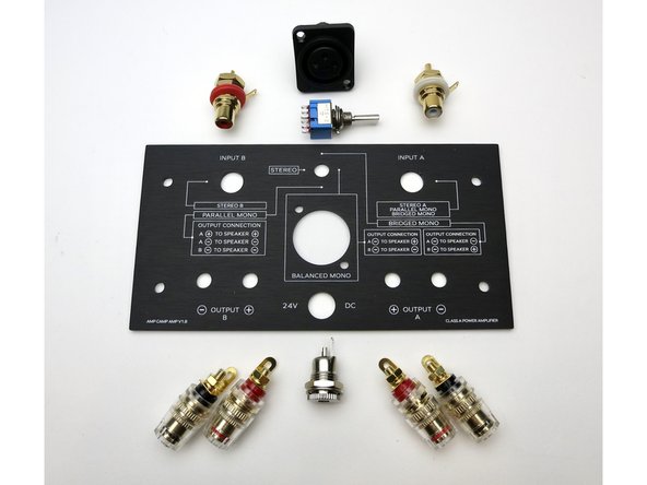
The only difference between v1.6 and v1.8 is the back panel, how the connections on the panel are wired, and the switch itself.
-
The circuit is identical. In fact, the rest of the amp aside the back panel is identical in v1.6 and v1.8
-
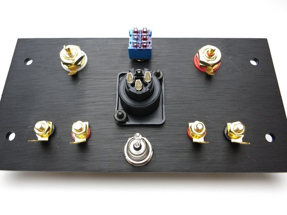
You can see the markings on the back panel, the switch positions on top then correspond with different boxes and the hookups are shown.
-
-
-
All of the connections to the outside are on the back panel. Follow the next few steps to get the jacks and connects properly installed and wired.
-
-
-
Insert wisdom here.
-
-
-
Insert wisdom here.
-
-
-
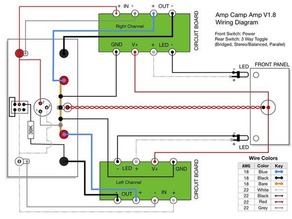
ACA v1.8 Wiring Diagram
-
Print this out and have it in front if you when building the amp.
-
-
-
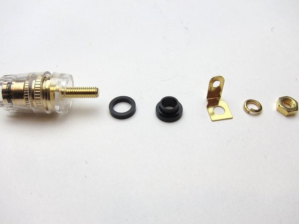
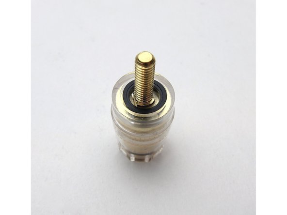
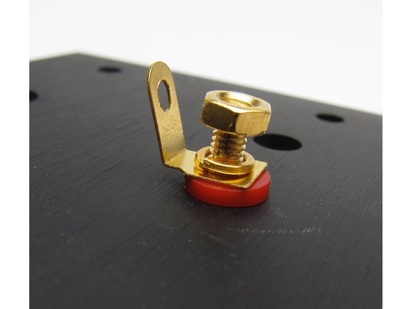
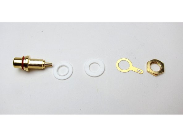
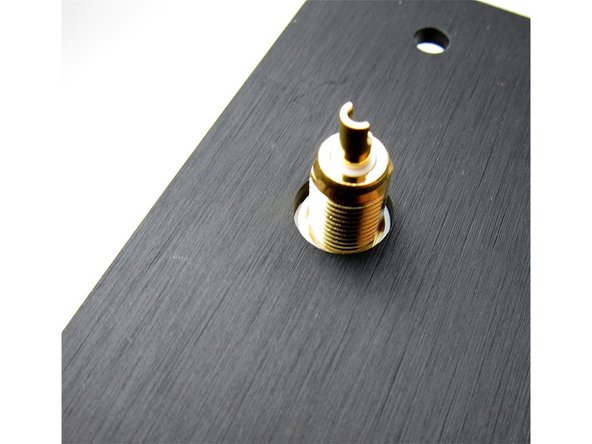
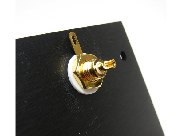
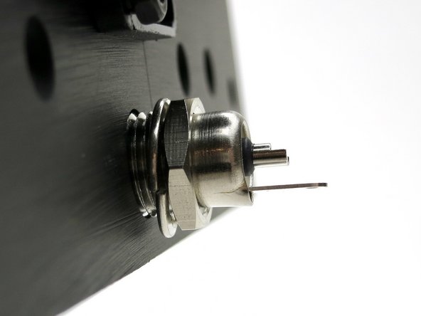
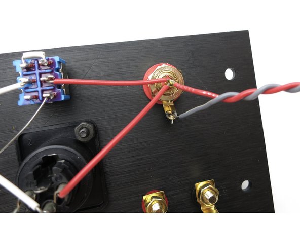
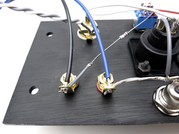
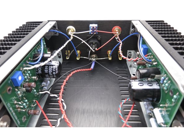
Photo 3 - please align the ground (outside) tab to the TOP
-
-
-
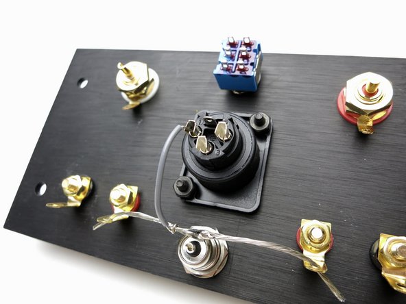
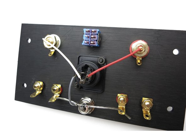
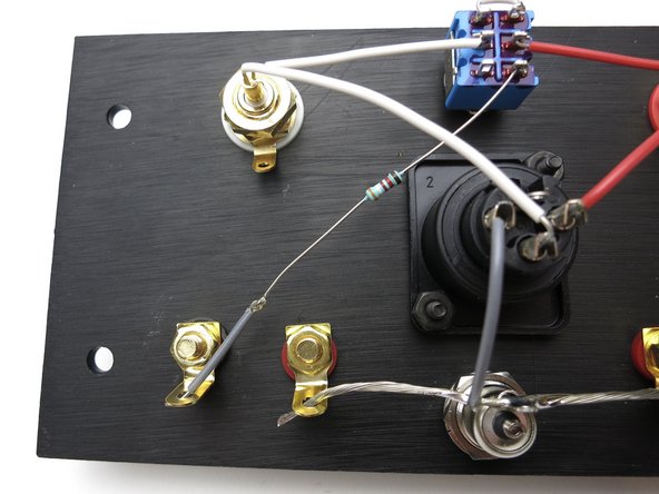
Photo 1 - Bare ground buss wire from both speaker reds to barrel ground tab. Ground buss to XLR pin 1 (grey wire)
-
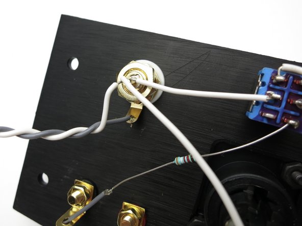
Photo 2 - Red RCA center to XLR pin 2 (red wire) White RCA center to XLR pin 3 (white wire)
-
Photo 3 - Small wire linking pins 1,2 of switch together.
-
Photo 3 - Red RCA center to pin 4 of switch. (Red wire)
-
Photo 3 - White RCA to pin 3 of switch. (white wire)
-
Helpful tip - Do not solder RCA yet.
-
-
-
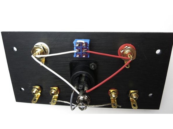
39K resistor needs a little bit of wire added to increase its length. Use whatever color you like.
-
Connect 39K resistor from pin 6 of switch to White channel black speaker post.
-
Photo 2 - Solder twisted pair grey/white wire, long enough to reach the PCB, to white channel RCA. Solder now.
-
Photo 3 - Solder twisted pair red/white wire, long enough to reach the PCB, to red channel RCA. Solder now.
-
-
-
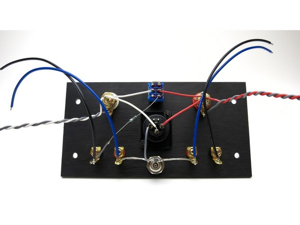
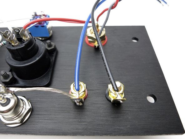
Solder blue heavy wire to red speaker posts.
-
Solder black heavy wire to black speaker posts.
-
-
-
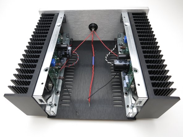
Everything shown here is identical in v1.6 and v1.8
-
-
-
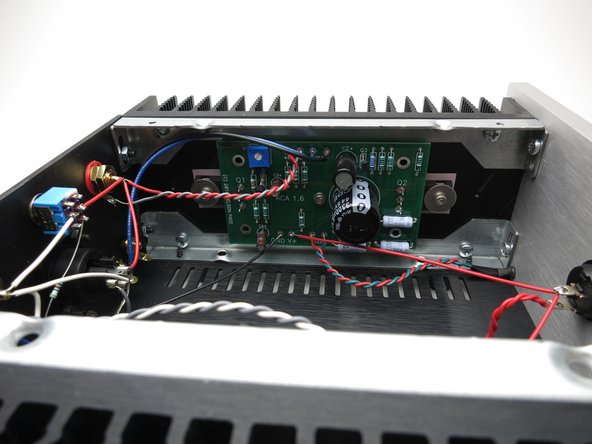
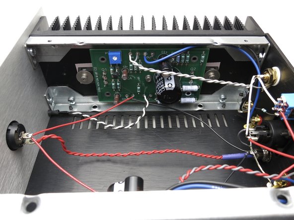
This shows the panel connected to the rest of the amp.
-
Barrel connector has the double red to the power switch on the center pin, and the black power GND wires to the tab.
-
RCA jacks wired grey to IN G and white & red to + IN
-
Blue speaker wire to + OUT, black wire to - OUT
-
Photos 2, 3 show the connections looking at the PCBs
-
-
-
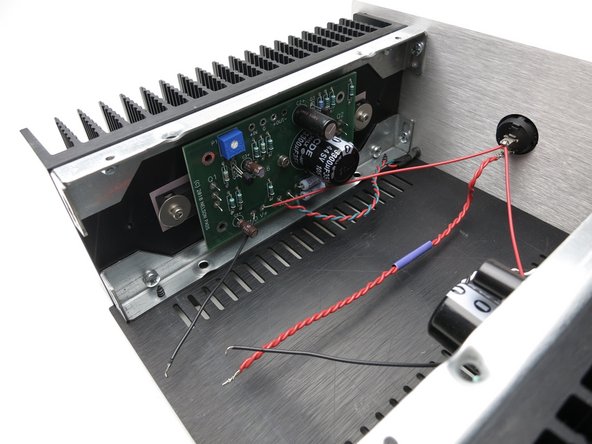
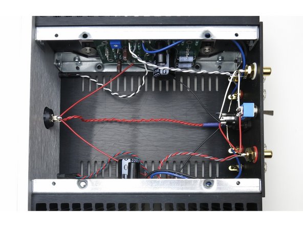
Top down photo of completed amp
-
-
-
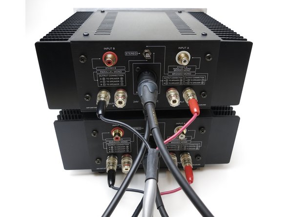
Using ACA 1.8 as stereo amp.
-
Switch to MIDDLE position.
-
RCAs used for input signal
-
Speakers attach red to red, black to black for each channel.
-
-
-
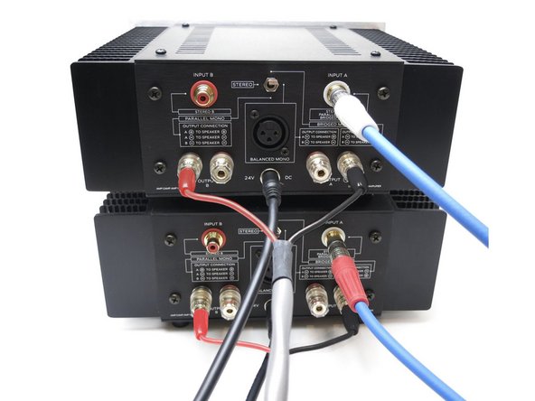
MONOBLOCK bridged with XLR input
-
Switch to MIDDLE position.
-
Input signal to XLR jack.
-
Speaker red to output A black.
-
Speaker black to output B black
-
-
-
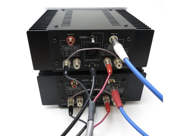
Monoblock bridged from RCA source
-
Switch UP
-
Input to White channel RCA (Input A)
-
Speaker red to output B black.
-
Speaker black to output A black.
-
-
-
MONOBLOCK Parallel connection from RCA
-
Input to input A
-
Switch DOWN
-
JUMPER both black speaker posts together. Use a piece of wire.
-
Speaker red to to output A red.
-
Speaker black to output B black.
-
-
-
Insert wisdom here.
-
-
-
Insert wisdom here.
-


Cancel: I did not complete this guide.
44 other people completed this guide.